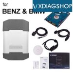
Yes, C4/C6 interfaces can often detect if the wrong type of OBD adapter cable is being used, which may result in communication failure. At DTS-MONACO.EDU.VN, we understand the frustration this can cause, and we’re here to provide clarity and solutions. This guide will walk you through understanding why this happens, how to identify the correct cables, and how to troubleshoot communication issues, ensuring you get the most out of your diagnostic and coding tasks. Understanding the nuances of OBD adapter cables is vital for any technician aiming to enhance their car coding skills.
Contents
- 1. Understanding C4/C6 Interfaces and OBD Adapter Cables
- What are C4/C6 Interfaces?
- What are OBD Adapter Cables?
- Why is Using the Correct Cable Important?
- How C4/C6 Interfaces Detect Incorrect Cables
- Consequences of Using the Wrong Cable
- 2. Identifying Different Types of OBD Adapter Cables
- Standard OBD-II Cables
- Specific Vehicle Brand Cables
- Protocol-Specific Cables
- Cables for Older Vehicles (OBD-I)
- How to Identify the Correct Cable
- Tips for Avoiding Cable Mismatches
- 3. Symptoms of Using the Wrong OBD Adapter Cable
- No Communication with the Vehicle
- Intermittent or Unstable Connection
- Incorrect Data Displayed
- ECU Errors or Damage
- Software or Firmware Issues
- Preventive Measures
- 4. Troubleshooting Communication Failures
- Step 1: Verify Cable and Connector Integrity
- Step 2: Confirm Cable Compatibility
- Step 3: Test the Connection
- Step 4: Advanced Troubleshooting
- Resources and Support
- 5. Preventing Future Communication Issues
- Invest in High-Quality Cables and Adapters
- Implement a Cable Management System
- Establish Clear Protocols for Cable Selection
- Regularly Inspect and Maintain Cables
- Stay Updated with Industry Standards and Technologies
- Resources and Support
- 6. The Role of Software in Detecting Cable Issues
- Real-Time Monitoring
- Error Messaging
- Automated Diagnostics
- Data Logging and Analysis
- Software Updates
- Resources and Support
- 7. Common Mistakes to Avoid When Selecting OBD Cables
- Ignoring Vehicle-Specific Requirements
- Using Generic Cables for Specialized Functions
- Neglecting Protocol Compatibility
- Overlooking Cable Quality
- Failing to Inspect Cables Regularly
- Ignoring Adapter Requirements
- Misinterpreting Error Messages
- Failing to Update Diagnostic Tool Software
- Resources and Support
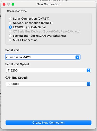
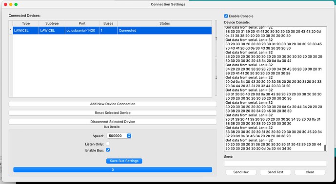
- 8. Integrating C4/C6 Interfaces with DTS-Monaco
- Software Installation
- Hardware Configuration
- DTS-Monaco Configuration
- Troubleshooting
- Best Practices
- Resources and Support
- 9. Advanced Techniques for Diagnosing Cable Issues
- Oscilloscope Analysis
- Time Domain Reflectometry (TDR)
- Frequency Domain Analysis
- CAN Bus Simulation
- Environmental Testing
- Resources and Support
- 10. Training and Certification for Automotive Diagnostics
- Foundational Knowledge
- Specialized Training
- Certification Programs
- Continuous Learning
- Resources and Support
- FAQ: C4/C6 Interfaces and OBD Adapter Cables
- 1. What is a C4/C6 interface?
- 2. What is an OBD adapter cable?
- 3. Can the wrong OBD adapter cable cause communication failure?
- 4. How can I identify the correct OBD adapter cable for my vehicle?
- 5. What are the symptoms of using the wrong OBD adapter cable?
- 6. How can I troubleshoot communication failures caused by OBD adapter cables?
- 7. What are some common mistakes to avoid when selecting OBD cables?
- 8. How does software help in detecting OBD adapter cable issues?
- 9. What advanced techniques can be used for diagnosing cable issues?
1. Understanding C4/C6 Interfaces and OBD Adapter Cables
Let’s dive into the world of C4/C6 interfaces and OBD adapter cables.
What are C4/C6 Interfaces?
C4 and C6 interfaces are essential tools for automotive diagnostics, programming, and coding. They act as a bridge between your diagnostic software (like DTS-Monaco) and the vehicle’s electronic control units (ECUs). These interfaces enable technicians to perform tasks such as reading diagnostic trouble codes (DTCs), flashing new software, and customizing vehicle settings. They are particularly useful in modern vehicles where complex electronic systems require precise and reliable communication tools.
What are OBD Adapter Cables?
OBD (On-Board Diagnostics) adapter cables are used to connect diagnostic tools, such as C4/C6 interfaces, to a vehicle’s OBD port. The OBD port is a standardized interface found in most modern vehicles, providing access to the vehicle’s diagnostic data. Different types of OBD adapter cables exist to support various communication protocols and vehicle models.
Why is Using the Correct Cable Important?
Using the correct OBD adapter cable is crucial for establishing reliable communication between the diagnostic tool and the vehicle. The wrong cable can lead to communication errors, incomplete data transfer, or even damage to the vehicle’s electronic systems. Proper cable selection ensures that the diagnostic tool can accurately read and write data to the vehicle’s ECUs, enabling effective diagnostics and coding.
How C4/C6 Interfaces Detect Incorrect Cables
C4/C6 interfaces are designed with built-in detection mechanisms to identify whether the correct OBD adapter cable is being used. These mechanisms include:
- Pin Configuration Checks: The interface verifies the pin configuration of the connected cable to ensure it matches the expected layout for the specific vehicle and communication protocol.
- Protocol Compatibility: The interface checks if the cable supports the required communication protocols (e.g., CAN, K-Line, J1850) used by the vehicle’s ECUs.
- Voltage Level Monitoring: The interface monitors the voltage levels on the communication lines to ensure they are within the acceptable range for reliable data transfer.
- Data Integrity Checks: The interface performs checks on the data transmitted through the cable to detect any errors or inconsistencies that may indicate a faulty or incorrect cable.
Consequences of Using the Wrong Cable
Using the wrong OBD adapter cable can lead to several negative consequences, including:
- Communication Failure: The interface may fail to establish a connection with the vehicle’s ECUs, preventing any diagnostic or coding operations.
- Data Corruption: Incorrect cable configurations can result in corrupted data being transmitted to or from the vehicle, leading to errors or malfunctions.
- ECU Damage: In severe cases, using the wrong cable can cause electrical damage to the vehicle’s ECUs, requiring costly repairs or replacements.
- Inaccurate Diagnostics: If communication is partially established, the diagnostic tool may provide inaccurate or incomplete diagnostic information, leading to incorrect diagnoses and repairs.
2. Identifying Different Types of OBD Adapter Cables
Identifying the correct OBD adapter cable is crucial for successful automotive diagnostics and coding. Here’s a breakdown of common cable types and how to distinguish them:
Standard OBD-II Cables
- Description: These are the most common cables, featuring a standard 16-pin connector that fits most modern vehicles (typically from 1996 onwards in the USA).
- Identification: Look for the 16-pin D-shaped connector.
- Use Cases: General diagnostics, reading trouble codes, viewing live data.
Specific Vehicle Brand Cables
- Description: Some manufacturers require specific cables with unique pin configurations or adapters to work with their vehicles.
- Identification: These cables often have additional connectors or adapters labeled for specific brands like Mercedes-Benz, BMW, or VAG (Volkswagen Audi Group).
- Use Cases: Advanced diagnostics, coding, and programming for specific vehicle brands.
Protocol-Specific Cables
- Description: Different vehicles use different communication protocols (e.g., CAN, K-Line, J1850). Some cables are designed to support specific protocols.
- Identification: These cables may be labeled with the protocol they support. Consult your vehicle’s documentation to determine the correct protocol.
- Use Cases: Vehicles that require specific communication protocols for diagnostics and coding.
Cables for Older Vehicles (OBD-I)
- Description: Older vehicles (pre-1996) use OBD-I, which requires different connectors and protocols than OBD-II.
- Identification: OBD-I cables have various connector types depending on the vehicle manufacturer, and they are not standardized like OBD-II.
- Use Cases: Diagnosing and servicing older, pre-1996 vehicles.
How to Identify the Correct Cable
- Check Vehicle Documentation: Consult your vehicle’s service manual or diagnostic documentation to identify the correct OBD cable type and any specific requirements.
- Use a Cable Identifier Tool: Some diagnostic tools come with cable identifier features that automatically detect the cable type when connected to the vehicle.
- Compare Pin Configurations: Carefully compare the pin configurations of the cable with the vehicle’s OBD port to ensure they match.
- Refer to Manufacturer Guidelines: Check the diagnostic tool manufacturer’s website or documentation for recommended cables and adapters for specific vehicle models.
Tips for Avoiding Cable Mismatches
- Label Your Cables: Clearly label each cable with its intended use and compatible vehicle models.
- Keep Cables Organized: Store cables in an organized manner to prevent confusion and accidental mismatches.
- Double-Check Before Connecting: Always double-check the cable type and compatibility before connecting it to the vehicle.
- Use High-Quality Cables: Invest in high-quality cables from reputable manufacturers to ensure reliable performance and prevent damage to your diagnostic equipment or vehicle.
- Training and Education: Enroll in training courses or workshops to learn about different OBD cable types and their proper use. DTS-MONACO.EDU.VN offers comprehensive training programs to enhance your diagnostic and coding skills.
3. Symptoms of Using the Wrong OBD Adapter Cable
Using the wrong OBD adapter cable can lead to various issues, impacting your ability to diagnose and service vehicles effectively. Here’s a detailed look at the common symptoms:
No Communication with the Vehicle
- Description: The most obvious symptom is the diagnostic tool failing to establish any communication with the vehicle’s electronic control units (ECUs).
- Indicators:
- The diagnostic tool displays an error message such as “No Communication,” “Link Error,” or “Unable to Connect.”
- The vehicle’s dashboard warning lights may not respond or display unusual behavior.
- The diagnostic tool does not recognize the vehicle’s VIN (Vehicle Identification Number).
- Why it Happens: The wrong cable may not support the communication protocol required by the vehicle or may have incorrect pin configurations, preventing data exchange.
Intermittent or Unstable Connection
- Description: The diagnostic tool connects to the vehicle sporadically, but the connection is unstable and frequently drops.
- Indicators:
- The diagnostic tool connects and disconnects intermittently.
- Data readings fluctuate or are incomplete.
- Error messages appear sporadically during diagnostic procedures.
- Why it Happens: A mismatched cable may create a weak or unreliable connection due to incorrect pin alignment or incompatible wiring.
Incorrect Data Displayed
- Description: The diagnostic tool connects to the vehicle and displays data, but the data is inaccurate or nonsensical.
- Indicators:
- Data values are out of range or do not match expected readings.
- Diagnostic trouble codes (DTCs) are inconsistent or do not align with the vehicle’s symptoms.
- Live data parameters are frozen or update very slowly.
- Why it Happens: The wrong cable may misinterpret data signals or transmit them incorrectly, leading to inaccurate readings.
ECU Errors or Damage
- Description: In severe cases, using an incorrect cable can cause errors in the vehicle’s ECUs or even physical damage.
- Indicators:
- ECUs become unresponsive or display error codes after connecting the diagnostic tool.
- The vehicle experiences electrical problems or malfunctions.
- Visible damage to the OBD port or ECU connectors.
- Why it Happens: Incorrect voltage levels or signal configurations from the wrong cable can damage sensitive electronic components in the ECUs.
Software or Firmware Issues
- Description: The diagnostic tool’s software or firmware may exhibit errors or become corrupted when used with the wrong cable.
- Indicators:
- The diagnostic tool freezes or crashes.
- Software features malfunction or become unavailable.
- Error messages related to software or firmware appear.
- Why it Happens: Incompatible cables can disrupt the data flow and cause errors in the diagnostic tool’s software, leading to malfunctions.
Preventive Measures
- Verify Cable Compatibility: Always double-check the cable’s compatibility with the vehicle’s make, model, and year before connecting it.
- Use the Correct Adapter: If required, use the appropriate adapter for specific vehicle models or communication protocols.
- Inspect Cables Regularly: Regularly inspect cables for damage, such as frayed wires or bent pins, which can cause connection issues.
- Follow Manufacturer Guidelines: Adhere to the diagnostic tool manufacturer’s recommendations for cable usage and compatibility.
- Professional Training: Enroll in professional training courses to learn about different OBD cable types and their proper use. DTS-MONACO.EDU.VN offers comprehensive training programs to enhance your diagnostic skills.
4. Troubleshooting Communication Failures
Experiencing communication failures during automotive diagnostics can be frustrating. Here’s a systematic approach to troubleshoot these issues effectively:
Step 1: Verify Cable and Connector Integrity
- Check the Cable:
- Physical Inspection: Look for any physical damage, such as cuts, frayed wires, or exposed conductors.
- Connector Condition: Ensure the connector pins are straight, not bent or broken, and free from corrosion.
- Cable Continuity: Use a multimeter to check the continuity of each wire within the cable to ensure there are no breaks.
- Check the OBD Port:
- Visual Inspection: Examine the OBD port on the vehicle for any signs of damage, debris, or corrosion.
- Pin Alignment: Verify that the pins inside the OBD port are properly aligned and not damaged.
- Clean the Port: Use a contact cleaner to remove any dirt or corrosion from the OBD port.
Step 2: Confirm Cable Compatibility
- Vehicle Specifications:
- Consult Documentation: Refer to the vehicle’s service manual or diagnostic documentation to identify the correct OBD cable type and any specific requirements.
- Communication Protocol: Determine the communication protocol used by the vehicle (e.g., CAN, K-Line, J1850) and ensure the cable supports it.
- Cable Specifications:
- Label Verification: Check the cable label or documentation to confirm its compatibility with the vehicle’s make, model, and year.
- Adapter Usage: If required, use the appropriate adapter for specific vehicle models or communication protocols.
- Cross-Reference:
- Online Resources: Use online cable compatibility charts or databases to cross-reference the cable with the vehicle.
- Manufacturer Support: Contact the diagnostic tool manufacturer or cable supplier for compatibility information.
Step 3: Test the Connection
- Basic Connection Test:
- Secure Connection: Ensure the cable is securely connected to both the diagnostic tool and the vehicle’s OBD port.
- Power Check: Verify that the diagnostic tool is powered on and functioning correctly.
- Diagnostic Tool Software:
- Software Updates: Ensure the diagnostic tool’s software is up to date with the latest version.
- Driver Installation: Verify that the correct drivers are installed for the OBD cable and diagnostic interface.
- Configuration Settings: Check the diagnostic tool’s configuration settings to ensure they match the vehicle’s specifications.
- Vehicle Ignition:
- Ignition On: Turn the vehicle’s ignition to the “ON” position (engine off) to enable communication with the ECUs.
- Battery Voltage: Ensure the vehicle’s battery has sufficient voltage to support diagnostic operations.
Step 4: Advanced Troubleshooting
- Multimeter Testing:
- Voltage Checks: Use a multimeter to check the voltage levels on the OBD port pins to ensure they are within the specified range.
- Ground Verification: Verify that the ground connection is solid and free from resistance.
- Oscilloscope Analysis:
- Signal Integrity: Use an oscilloscope to analyze the communication signals on the OBD port to identify any distortions or anomalies.
- Protocol Verification: Confirm that the communication protocol is being transmitted correctly.
- ECU Reset:
- Disconnect Battery: Disconnect the vehicle’s battery for a few minutes to reset the ECUs and clear any temporary errors.
- Reconnect and Test: Reconnect the battery and attempt to establish communication with the diagnostic tool.
- Professional Assistance:
- Expert Consultation: If you are unable to resolve the communication failure, seek assistance from a qualified automotive technician or diagnostic specialist.
- Technical Support: Contact the diagnostic tool manufacturer or cable supplier for technical support.
Resources and Support
- DTS-MONACO.EDU.VN: Offers comprehensive training programs and resources to enhance your diagnostic and coding skills.
- Online Forums: Participate in online automotive diagnostic forums to share experiences and seek advice from other technicians.
- Technical Documentation: Refer to technical documentation and service manuals for detailed troubleshooting procedures.
5. Preventing Future Communication Issues
Preventing communication issues is key to efficient and reliable automotive diagnostics. Here’s how to minimize problems in the future:
Invest in High-Quality Cables and Adapters
- Reputable Brands:
- Purchase cables and adapters from reputable manufacturers known for quality and reliability.
- Avoid generic or low-cost options that may not meet industry standards.
- Durability:
- Choose cables with durable construction, including sturdy connectors and robust wiring.
- Look for cables with strain relief to prevent damage from bending or pulling.
- Certifications:
- Ensure cables and adapters are certified to meet relevant industry standards (e.g., SAE, ISO).
- Check for compliance with vehicle manufacturer specifications.
Implement a Cable Management System
- Labeling:
- Clearly label each cable with its intended use, compatible vehicle models, and communication protocols.
- Use color-coded labels for easy identification.
- Organization:
- Store cables in an organized manner to prevent tangling and damage.
- Use cable organizers, racks, or storage bins to keep cables neat and accessible.
- Storage Conditions:
- Store cables in a clean, dry environment to prevent corrosion and degradation.
- Avoid exposing cables to extreme temperatures or direct sunlight.
Establish Clear Protocols for Cable Selection
- Vehicle Documentation:
- Always consult the vehicle’s service manual or diagnostic documentation to identify the correct cable type and any specific requirements.
- Create a reference guide or checklist for common vehicle models and their corresponding cables.
- Training and Education:
- Provide training for technicians on proper cable selection and usage.
- Include information on different communication protocols and their compatibility with various cable types.
- Verification Process:
- Implement a verification process to ensure the correct cable is selected before connecting to the vehicle.
- Use cable identifier tools or software to automatically detect the cable type.
Regularly Inspect and Maintain Cables
- Visual Inspections:
- Periodically inspect cables for signs of damage, such as cuts, frayed wires, or exposed conductors.
- Check connectors for bent or broken pins, corrosion, or loose connections.
- Cleaning:
- Clean cables and connectors regularly using a contact cleaner to remove dirt, debris, and corrosion.
- Avoid using abrasive cleaners or solvents that can damage the cable insulation or connector materials.
- Testing:
- Use a multimeter to check the continuity of each wire within the cable to ensure there are no breaks.
- Test the cable’s performance with a diagnostic tool to verify its functionality.
Stay Updated with Industry Standards and Technologies
- Continuous Learning:
- Stay informed about the latest industry standards, diagnostic technologies, and vehicle communication protocols.
- Attend training courses, workshops, and conferences to enhance your knowledge and skills.
- Software Updates:
- Keep your diagnostic tool’s software up to date with the latest versions to ensure compatibility with new vehicle models and communication protocols.
- Subscribe to industry publications and online resources to stay informed about emerging trends and best practices.
Resources and Support
- DTS-MONACO.EDU.VN: Offers comprehensive training programs and resources to enhance your diagnostic and coding skills.
- Online Forums: Participate in online automotive diagnostic forums to share experiences and seek advice from other technicians.
- Technical Documentation: Refer to technical documentation and service manuals for detailed troubleshooting procedures.
 Screen Shot 2024-04-05 at 6.51.13 PM
6. The Role of Software in Detecting Cable Issues
Software plays a crucial role in detecting OBD adapter cable issues, enhancing diagnostic accuracy and preventing potential damage.
Real-Time Monitoring
- Voltage Monitoring: Diagnostic software continuously monitors voltage levels on the communication lines. Deviations from expected values can indicate cable problems.
- Data Integrity Checks: Software algorithms verify the integrity of transmitted data, identifying errors caused by faulty cables.
- Protocol Compliance: Software confirms that the cable supports the necessary communication protocols (e.g., CAN, K-Line) for the vehicle’s ECUs.
Error Messaging
- Clear Error Codes: When a cable issue is detected, the software generates specific error codes, helping technicians pinpoint the problem.
- Descriptive Messages: User-friendly messages explain the nature of the cable issue, suggesting possible causes and solutions.
- Troubleshooting Guides: Integrated troubleshooting guides provide step-by-step instructions for resolving cable-related problems.
Automated Diagnostics
- Cable Identification: Advanced software automatically identifies the type of OBD adapter cable connected to the vehicle.
- Compatibility Checks: Software verifies that the cable is compatible with the vehicle’s make, model, and year, preventing mismatches.
- Diagnostic Routines: Automated diagnostic routines test the cable’s functionality, identifying issues such as short circuits or open connections.
Data Logging and Analysis
- Data Logging: Software records communication data, allowing technicians to analyze patterns and identify intermittent cable issues.
- Historical Analysis: Historical data helps track recurring problems and identify potential cable failures.
- Reporting: Detailed reports summarize diagnostic findings, including cable-related issues, aiding in troubleshooting and repair.
Software Updates
- Firmware Updates: Regular firmware updates enhance the diagnostic tool’s ability to detect cable issues.
- Protocol Support: Updates ensure compatibility with the latest vehicle communication protocols and cable technologies.
- Bug Fixes: Software updates address known issues and improve the overall reliability of cable detection.
Resources and Support
- DTS-MONACO.EDU.VN: Offers training programs and resources to enhance your diagnostic software skills.
- Online Forums: Engage in online forums to discuss software-related issues and solutions with other technicians.
- Technical Documentation: Refer to software documentation and service manuals for detailed troubleshooting procedures.
 Screen Shot 2024-04-05 at 6.51.48 PM
7. Common Mistakes to Avoid When Selecting OBD Cables
Selecting the correct OBD cable is essential for accurate diagnostics and coding. Here are common mistakes to avoid:
Ignoring Vehicle-Specific Requirements
- Mistake: Assuming all OBD-II cables are universally compatible.
- Solution: Always consult the vehicle’s service manual or diagnostic documentation to identify specific cable requirements.
- Example: Some European vehicles require specific adapter cables for full diagnostic functionality.
Using Generic Cables for Specialized Functions
- Mistake: Using a standard OBD-II cable for advanced coding or programming tasks.
- Solution: Use cables designed for specific functions, such as those supporting J2534 pass-through programming.
- Example: Reprogramming an ECU often requires a specialized cable that supports specific protocols.
Neglecting Protocol Compatibility
- Mistake: Overlooking the communication protocol (e.g., CAN, K-Line, J1850) required by the vehicle.
- Solution: Ensure the cable supports the necessary communication protocols for the vehicle’s ECUs.
- Example: Older vehicles may use J1850, while newer vehicles typically use CAN.
Overlooking Cable Quality
- Mistake: Purchasing low-quality cables to save money.
- Solution: Invest in high-quality cables from reputable manufacturers to ensure reliable performance.
- Example: Poorly shielded cables can introduce noise and interference, leading to inaccurate readings.
Failing to Inspect Cables Regularly
- Mistake: Neglecting to inspect cables for damage or wear.
- Solution: Regularly inspect cables for cuts, frayed wires, and bent pins.
- Example: A damaged cable can cause intermittent connections or complete communication failure.
Ignoring Adapter Requirements
- Mistake: Not using necessary adapters for specific vehicle models or functions.
- Solution: Use the correct adapters as specified by the vehicle manufacturer or diagnostic tool provider.
- Example: Some BMW models require a specific adapter for accessing certain ECUs.
Misinterpreting Error Messages
- Mistake: Ignoring or misinterpreting error messages from the diagnostic tool.
- Solution: Carefully read and understand error messages to identify potential cable issues.
- Example: An error message indicating “No Communication” may suggest a cable incompatibility or a damaged connection.
Failing to Update Diagnostic Tool Software
- Mistake: Not keeping the diagnostic tool’s software up to date.
- Solution: Regularly update the software to ensure compatibility with new vehicle models and cable types.
- Example: Outdated software may not recognize newer cable technologies, leading to communication problems.
Resources and Support
- DTS-MONACO.EDU.VN: Offers training programs and resources to enhance your diagnostic and coding skills.
- Online Forums: Engage in online forums to discuss common mistakes and solutions with other technicians.
- Technical Documentation: Refer to technical documentation and service manuals for detailed guidance on cable selection and usage.
8. Integrating C4/C6 Interfaces with DTS-Monaco
Integrating C4/C6 interfaces with DTS-Monaco requires careful configuration to ensure seamless communication.
Software Installation
- DTS-Monaco Software:
- Installation: Install DTS-Monaco on a compatible Windows operating system.
- Activation: Activate the software using a valid license key.
- Updates: Regularly update to the latest version for bug fixes and new features.
- C4/C6 Drivers:
- Driver Installation: Install the necessary drivers for the C4/C6 interface.
- Compatibility: Ensure drivers are compatible with your operating system.
- Updates: Keep drivers updated for optimal performance.
Hardware Configuration
- Interface Connection:
- USB Connection: Connect the C4/C6 interface to your computer via USB.
- Power Supply: Ensure the interface has a stable power supply.
- Vehicle Connection: Connect the interface to the vehicle’s OBD-II port.
- Interface Settings:
- COM Port: Identify the COM port assigned to the interface in Device Manager.
- Baud Rate: Configure the baud rate in DTS-Monaco to match the interface settings.
- Latency: Adjust latency settings if needed for stable communication.
DTS-Monaco Configuration
- Interface Selection:
- Select Interface: In DTS-Monaco, select the C4/C6 interface as the communication device.
- Configuration: Configure the interface settings, including COM port and baud rate.
- Test Connection: Test the connection to ensure the software recognizes the interface.
- Project Setup:
- Vehicle Selection: Choose the correct vehicle model from the DTS-Monaco database.
- ECU Selection: Select the specific ECU you want to communicate with.
- Communication Protocols: Verify the correct communication protocols are selected.
Troubleshooting
- Connection Issues:
- Driver Problems: Check for driver conflicts or installation errors.
- COM Port Conflicts: Resolve any COM port conflicts with other devices.
- Cable Integrity: Ensure the OBD-II cable is in good condition and properly connected.
- Software Errors:
- Compatibility Issues: Verify that DTS-Monaco is compatible with your operating system and interface.
- Configuration Errors: Double-check the software configuration settings.
- Log Files: Review log files for error messages that can help diagnose the problem.
Best Practices
- Stable Power: Use a stable power source to prevent interruptions during coding.
- Backup: Always back up ECU data before making changes.
- Documentation: Keep detailed records of all coding changes.
Resources and Support
- DTS-MONACO.EDU.VN: Offers training programs and resources to enhance your diagnostic and coding skills.
- Online Forums: Engage in online forums to discuss integration issues and solutions with other technicians.
- Technical Documentation: Refer to DTS-Monaco documentation and service manuals for detailed guidance.
 Screen Shot 2024-04-05 at 6.52.11 PM
9. Advanced Techniques for Diagnosing Cable Issues
Advanced diagnostic techniques can help pinpoint elusive OBD adapter cable issues.
Oscilloscope Analysis
- Signal Integrity:
- Use an oscilloscope to analyze the waveform of signals transmitted through the cable.
- Look for signal distortions, noise, or attenuation that may indicate cable problems.
- Protocol Verification:
- Verify that the cable is transmitting the correct communication protocols (e.g., CAN, K-Line, J1850).
- Check for timing issues or protocol violations.
Time Domain Reflectometry (TDR)
- Fault Location:
- Use a TDR to locate faults within the cable, such as shorts, opens, or impedance mismatches.
- TDR sends a pulse through the cable and analyzes the reflections to identify discontinuities.
- Cable Length:
- Measure the cable length to ensure it meets specifications.
- Excessive length can cause signal degradation.
Frequency Domain Analysis
- Impedance Matching:
- Use a network analyzer to measure the cable’s impedance across a range of frequencies.
- Ensure the cable is properly impedance-matched to the diagnostic tool and vehicle.
- Attenuation:
- Measure the cable’s attenuation to determine signal loss at different frequencies.
- Excessive attenuation can indicate cable degradation.
CAN Bus Simulation
- Stress Testing:
- Use a CAN bus simulator to generate test signals and verify the cable’s performance under stress.
- Simulate various communication scenarios to identify potential weaknesses.
- Error Injection:
- Inject errors into the CAN bus to test the cable’s ability to handle faults.
- Verify that the diagnostic tool can detect and report errors correctly.
Environmental Testing
- Temperature Cycling:
- Subject the cable to temperature cycling to simulate real-world conditions.
- Check for changes in performance or physical damage.
- Vibration Testing:
- Vibrate the cable to simulate the effects of vehicle motion.
- Look for intermittent connections or signal disruptions.
Resources and Support
- DTS-MONACO.EDU.VN: Offers training programs and resources to enhance your diagnostic and coding skills.
- Online Forums: Engage in online forums to discuss advanced diagnostic techniques with other technicians.
- Technical Documentation: Refer to technical documentation and service manuals for detailed guidance on cable testing and analysis.
10. Training and Certification for Automotive Diagnostics
Proper training and certification are essential for mastering automotive diagnostics.
Foundational Knowledge
- Basic Electronics:
- Understand basic electronic components and circuits.
- Learn how to use multimeters, oscilloscopes, and other diagnostic tools.
- Vehicle Systems:
- Study vehicle systems, including engine, transmission, brakes, and electrical.
- Learn how these systems interact and how to diagnose common problems.
- OBD-II Standards:
- Become familiar with OBD-II standards and protocols.
- Understand diagnostic trouble codes (DTCs) and their meanings.
Specialized Training
- Advanced Diagnostics:
- Learn advanced diagnostic techniques, such as CAN bus analysis and ECU programming.
- Study vehicle communication protocols, including CAN, K-Line, and J1850.
- Software Training:
- Get hands-on training with diagnostic software, such as DTS-Monaco.
- Learn how to use the software to diagnose and troubleshoot vehicle problems.
- Vehicle-Specific Training:
- Attend training courses focused on specific vehicle makes and models.
- Learn about common problems and diagnostic procedures for these vehicles.
Certification Programs
- ASE Certification:
- Achieve Automotive Service Excellence (ASE) certification to demonstrate your skills and knowledge.
- Choose certifications relevant to your area of expertise, such as electrical, engine, or brakes.
- Manufacturer Certifications:
- Obtain certifications from vehicle manufacturers, such as Mercedes-Benz, BMW, or Ford.
- These certifications validate your expertise in diagnosing and repairing their vehicles.
Continuous Learning
- Stay Updated:
- Stay informed about the latest diagnostic technologies and techniques.
- Attend industry conferences, workshops, and webinars.
- Online Resources:
- Utilize online forums, technical articles, and training videos to expand your knowledge.
- Participate in online communities to share experiences and learn from others.
Resources and Support
- DTS-MONACO.EDU.VN: Offers comprehensive training programs and resources to enhance your diagnostic and coding skills.
- Online Forums: Engage in online forums to discuss training and certification options with other technicians.
- Technical Documentation: Refer to technical documentation and service manuals for detailed guidance on diagnostic procedures.
 Screen Shot 2024-04-05 at 6.52.21 PM
FAQ: C4/C6 Interfaces and OBD Adapter Cables
Here are some frequently asked questions about C4/C6 interfaces and OBD adapter cables:
1. What is a C4/C6 interface?
A C4/C6 interface is a diagnostic tool that connects to a vehicle’s OBD port, allowing technicians to read diagnostic data, perform coding, and program electronic control units (ECUs).
2. What is an OBD adapter cable?
An OBD adapter cable connects the diagnostic tool (like a C4/C6 interface) to the vehicle’s OBD port, facilitating communication between them.
3. Can the wrong OBD adapter cable cause communication failure?
Yes, using the wrong OBD adapter cable can lead to communication failure due to incompatible pin configurations or unsupported communication protocols.
4. How can I identify the correct OBD adapter cable for my vehicle?
Consult your vehicle’s service manual or diagnostic documentation to identify the correct cable type and any specific requirements.
5. What are the symptoms of using the wrong OBD adapter cable?
Symptoms include no communication with the vehicle, intermittent connections, incorrect data display, and potential ECU errors or damage.
6. How can I troubleshoot communication failures caused by OBD adapter cables?
Check cable integrity, verify cable compatibility, test the connection, and use advanced techniques like oscilloscope analysis to diagnose the issue.
7. What are some common mistakes to avoid when selecting OBD cables?
Avoid ignoring vehicle-specific requirements, using generic cables for specialized functions, and neglecting protocol compatibility.
8. How does software help in detecting OBD adapter cable issues?
Software monitors voltage levels, performs data integrity checks, and provides error messaging to identify cable-related problems.
9. What advanced techniques can be used for diagnosing cable issues?
Advanced techniques include oscilloscope analysis, time domain reflectometry (TDR), and CAN bus simulation.
