
Yes, ECOM can indeed be leveraged to diagnose issues within variable valve lift systems like Camtronic, offering a powerful diagnostic avenue. At DTS-MONACO.EDU.VN, we provide the resources and expertise to master ECOM and other diagnostic tools, empowering you to efficiently troubleshoot and resolve complex automotive problems, including those related to variable valve timing and lift systems, ensuring optimal engine performance and longevity. Dive in to discover the possibilities and potential benefits of enhancing your diagnostic capabilities, optimizing vehicle performance, and mastering engine control strategies.
Contents
- 1. Understanding Variable Valve Lift Systems: Camtronic and Beyond
- 1.1. The Basics of VVT and VVL
- 1.2. Camtronic: Mercedes-Benz’s VVL System
- 1.3. The Benefits of VVT/VVL Systems
- 1.4. Common VVT/VVL Systems in the Automotive Industry
- 2. How ECOM Aids in Diagnosing VVT/VVL Issues
- 2.1. Reading Diagnostic Trouble Codes (DTCs)
- 2.2. Monitoring Live Data
- 2.3. Performing Actuator Tests
- 2.4. Adaptation and Calibration
- 3. Step-by-Step Diagnostic Process Using ECOM for Camtronic Systems
- 3.1. Connect the ECOM Interface
- 3.2. Read Diagnostic Trouble Codes (DTCs)
- 3.3. Check Live Data
- 3.4. Perform Actuator Tests
- 3.5. Inspect Components
- 3.6. Perform Further Testing
- 3.7. Repair or Replace Components
- 3.8. Perform Adaptation or Calibration
- 3.9. Clear DTCs and Verify Repair
- 4. Common Issues and Troubleshooting Tips for Camtronic Systems
- 4.1. Solenoid Valve Failures
- 4.2. Actuator Problems
- 4.3. Oil Pressure Issues
- 4.4. Wiring and Connector Problems
- 4.5. Sludge Buildup
- 5. The Role of DTS-MONACO.EDU.VN in Mastering ECOM and Car Coding
- 5.1. In-Depth Training Courses
- 5.2. Comprehensive Resources and Documentation
- 5.3. Expert Support and Guidance
- 5.4. Software and Hardware Solutions
- 6. Advanced Techniques for Diagnosing Camtronic Systems
- 6.1. Using Oscilloscopes for Signal Analysis
- 6.2. Performing Pressure Drop Tests
- 6.3. Utilizing Advanced Diagnostic Software Features
- 6.4. Conducting Component-Level Testing
- 7. Maintaining and Preventing Camtronic System Issues
- 7.1. Regular Oil Changes
- 7.2. Inspecting and Replacing Components
- 7.3. Performing System Flushes
- 7.4. Keeping Up-to-Date with Technical Service Bulletins (TSBs)
- 8. Case Studies: Diagnosing Camtronic Issues with ECOM
- 8.1. Case Study 1: P0011 Code on a Mercedes-Benz C-Class
- 8.2. Case Study 2: Poor Engine Performance on a Mercedes-Benz E-Class
- 8.3. Case Study 3: Engine Noise on a Mercedes-Benz S-Class
- 9. Future Trends in VVT/VVL Diagnostics
- 9.1. Enhanced Diagnostic Software Features
- 9.2. Integration with Vehicle Manufacturers’ Diagnostic Systems
- 9.3. Increased Use of Wireless Technology
- 9.4. Focus on Predictive Maintenance
- 10. FAQ: Diagnosing Camtronic and VVT/VVL Systems
1. Understanding Variable Valve Lift Systems: Camtronic and Beyond
Variable Valve Timing (VVT) and Variable Valve Lift (VVL) technologies are crucial for modern engine efficiency and performance. These systems dynamically adjust valve timing and lift, optimizing engine performance across various RPMs and loads. A conventional camshaft has fixed valve lift, duration and timing, so the grind is always a compromise between fuel economy, performance and emissions. But with cam phasing VVT, duration, valve overlap and timing can be changed on the go to optimize engine performance at different RPMs, loads and operating conditions. Camtronic, used by Mercedes-Benz, is one such system. Let’s break down how these systems work and why they’re important.
1.1. The Basics of VVT and VVL
VVT systems adjust the timing of when valves open and close, while VVL systems control how far the valves open. Both technologies work to improve engine breathing and combustion efficiency. Cam phasing systems essentially rotate the camshaft fore or aft to advance or retard timing. This differs from other VVT systems such as Honda’s VTEC and Nissan’s VVL that are “cam changing” systems. In a cam changing VVT system, the position of the rocker arms changes when oil pressure is applied so the rockers will follow a different set of lobes on the cam for increased lift, duration and power.
- VVT (Variable Valve Timing): Optimizes valve timing for better throttle response and torque at low RPMs, and increased power at higher engine speeds.
- VVL (Variable Valve Lift): Modulates the valve lift to control the amount of air and fuel entering the cylinders, enhancing fuel efficiency and reducing emissions.
1.2. Camtronic: Mercedes-Benz’s VVL System
Camtronic is Mercedes-Benz’s implementation of variable valve lift technology. It enhances engine efficiency and performance by adjusting the valve lift based on driving conditions. Some applications combine both cam phasing and cam changing such as Audi’s Valvelift, BMW’s VANOS, Honda’s i-VTEC, Mercedes’ Camtronic, Porsche’s Variocam Plus and Toyota’s VVTL-i.
1.3. The Benefits of VVT/VVL Systems
- Improved Fuel Efficiency: Adjusting valve lift and timing optimizes combustion, reducing fuel consumption.
- Enhanced Performance: Optimized engine breathing leads to better power output across the RPM range.
- Reduced Emissions: Precise control over combustion reduces harmful emissions.
- Eliminate the need for an EGR valve: Valve timing can also be retarded when the engine is under load to reduce NOx emissions.
1.4. Common VVT/VVL Systems in the Automotive Industry
Several manufacturers use variations of VVT and VVL technologies:
| Manufacturer | System Name | Features |
|---|---|---|
| Honda | i-VTEC | Combines VVT and VVL for optimized performance and efficiency. |
| BMW | Valvetronic | Continuously variable valve lift, offering precise control over airflow into the engine. Some applications also have the ability to continuously vary valve lift on the go, such as BMW’s Valvetronic, Nissan’s CVTC and VVEL and Toyota’s Valvematic. |
| Toyota | Valvematic | Valvematic varies valve lift to control intake volume, improving efficiency. |
| Nissan | CVTC/VVEL | CVTC adjusts valve timing, while VVEL controls valve lift for improved engine response and efficiency. |
| Audi | Valvelift System | Varies valve lift in two stages to optimize performance and fuel economy. |
| Porsche | Variocam Plus | Adjusts both valve timing and lift for improved engine performance. |
2. How ECOM Aids in Diagnosing VVT/VVL Issues
ECOM (ECU Communication) is a protocol and interface used to communicate with a vehicle’s electronic control units (ECUs). It allows technicians to read diagnostic trouble codes (DTCs), monitor live data, and perform calibrations and adaptations. On DOHC engines with separate cam phasers for the intake and exhaust cams, the powertrain control module can independently advance or retard the intake and exhaust cams. This changes the centerline between the cams and the lobe separation angle, which, in turn, changes valve overlap and duration. On SOHC and pushrod engines that have VVT, the same cam operates both the intake and exhaust valves, so advancing or retarding the cam simultaneously changes both the intake and exhaust timing.
2.1. Reading Diagnostic Trouble Codes (DTCs)
ECOM enables technicians to retrieve DTCs related to the VVT/VVL system, helping pinpoint potential issues. These codes can indicate problems with:
- Camshaft position sensors
- Solenoid valves
- Actuators
- Mechanical components within the VVT/VVL system
Example DTCs:
- P0011: “A” Camshaft Position – Timing Over-Advanced or System Performance (Bank 1)
- P0014: “B” Camshaft Position – Timing Over-Advanced or System Performance (Bank 1)
- P0020: “A” Camshaft Position Actuator Circuit/Open (Bank 2)
- P0023: “B” Camshaft Position Actuator Circuit/Open (Bank 2)
2.2. Monitoring Live Data
ECOM allows real-time monitoring of VVT/VVL system parameters, providing valuable insights into their operation. Key parameters to monitor include:
- Camshaft position
- Valve lift position
- Solenoid duty cycle
- Oil pressure
2.3. Performing Actuator Tests
Actuator tests can be performed using ECOM to verify the functionality of VVT/VVL components. These tests command the actuators to specific positions and monitor their response. Most of the VVT systems you are likely to encounter are those with hydraulically actuated cam phasers, although a few (such as Lexus) use an electric actuator to advance or retard cam timing. The cam phaser changes camshaft and valve timing by rotating the relative position of the camshaft slightly fore or aft compared to its normal base timing setting. The phaser is part of the cam drive system and is mounted on the cam drive gear or sprocket.
Example Actuator Tests:
- VVT Solenoid Activation: Activate the solenoid to verify it changes the camshaft position.
- Valve Lift Control: Command the valve lift actuator to different positions to check its response.
2.4. Adaptation and Calibration
Some VVT/VVL systems require adaptation or calibration after component replacement. ECOM facilitates these procedures, ensuring the system functions correctly with the new components.
- Camshaft Position Sensor Calibration: Align the camshaft position sensor signal with the actual camshaft position.
- Valve Lift System Adaptation: Adjust the valve lift system parameters to match the engine’s specifications.
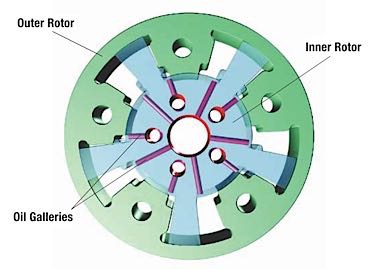 Volkswagen camphaser: The rotor inside the cam phaser changes position when oil pressure is routed into the chambers. This rotates the cam to change valve timing.
Volkswagen camphaser functioning by using rotor inside to alter valve timing.
3. Step-by-Step Diagnostic Process Using ECOM for Camtronic Systems
To effectively diagnose Camtronic issues using ECOM, follow these steps:
3.1. Connect the ECOM Interface
- Connect the ECOM interface to the vehicle’s OBD-II port.
- Ensure the vehicle’s ignition is turned on.
3.2. Read Diagnostic Trouble Codes (DTCs)
- Use the diagnostic software to read and record any DTCs related to the engine or VVT/VVL system. As simple as it all sounds, any number of things may set a VVT-related fault code:
- Research the DTCs to understand the potential causes and affected components.
3.3. Check Live Data
- Monitor live data parameters such as camshaft position, valve lift position, and solenoid duty cycle.
- Compare the live data with the manufacturer’s specifications to identify any discrepancies.
3.4. Perform Actuator Tests
- Use the diagnostic software to perform actuator tests on the Camtronic components. There are several basic designs:
- Verify that the actuators respond correctly to the commands and that their movement is within the specified range.
3.5. Inspect Components
-
Visually inspect the Camtronic system components, including:
- Solenoid valves
- Actuators
- Wiring and connectors
-
Look for signs of damage, wear, or corrosion.
3.6. Perform Further Testing
-
If the issue is not immediately apparent, perform additional tests such as:
- Oil pressure test: Check the oil pressure at the Camtronic system to ensure it meets the manufacturer’s specifications.
- Continuity test: Check the continuity of the wiring between the ECU and the Camtronic components.
3.7. Repair or Replace Components
- Based on the diagnostic results, repair or replace any faulty components.
- Ensure that all replacement parts meet the manufacturer’s specifications.
3.8. Perform Adaptation or Calibration
- After replacing any components, perform any necessary adaptation or calibration procedures using the ECOM interface.
- This ensures that the Camtronic system functions correctly with the new components.
3.9. Clear DTCs and Verify Repair
- Clear any stored DTCs and perform a test drive to verify that the issue has been resolved.
- Monitor the live data parameters to confirm that the Camtronic system is functioning correctly.
4. Common Issues and Troubleshooting Tips for Camtronic Systems
Several issues can arise with Camtronic systems. Here are some common problems and troubleshooting tips.
4.1. Solenoid Valve Failures
Problem: Solenoid valves can fail due to electrical issues or mechanical wear, preventing proper oil flow to the Camtronic actuators. Electrical problems with the voltage supply, ground connection or wiring harness to the oil flow control solenoid(s). If a solenoid fails to open and close when commanded to do so, it will prevent oil pressure from reaching the cam phaser. This will also set a camshaft position error fault code.
Troubleshooting Tips:
- Check the solenoid valve’s electrical resistance using a multimeter.
- Verify that the solenoid valve is receiving power and ground.
- Clean or replace the solenoid valve if it is clogged or damaged.
4.2. Actuator Problems
Problem: Actuators can become worn or damaged, leading to improper valve lift control. Physical wear or damage inside the cam phaser housing may prevent it from rotating, cause it to stick or make the unit noisy. A broken return spring may prevent it from returning to base timing.
Troubleshooting Tips:
- Visually inspect the actuators for any signs of damage or wear.
- Perform actuator tests using ECOM to verify their functionality.
- Replace the actuators if they are not functioning correctly.
4.3. Oil Pressure Issues
Problem: Low oil pressure can prevent the Camtronic system from functioning correctly, leading to poor engine performance. Low oil pressure due to a low oil level in the crankcase, worn oil pump, worn main bearings or worn cam bearings. Hydraulically actuated cam phasers require good oil pressure to change their position. If they don’t get it, cam timing won’t change. Check the oil level in the crankcase, and, if it is low, add oil and check for oil leaks. If adding oil doesn’t remedy the situation, the phasers may not be receiving adequate oil pressure due to the other conditions just mentioned.
Troubleshooting Tips:
- Check the engine oil level and ensure it is within the recommended range.
- Connect an oil pressure gauge to the Camtronic system to verify the oil pressure.
- Inspect the oil pump and oil filter for any signs of damage or clogging.
4.4. Wiring and Connector Problems
Problem: Damaged or corroded wiring and connectors can disrupt the signals between the ECU and the Camtronic components.
Troubleshooting Tips:
- Visually inspect the wiring and connectors for any signs of damage or corrosion.
- Check the continuity of the wiring using a multimeter.
- Clean or replace any damaged or corroded wiring and connectors.
4.5. Sludge Buildup
Problem: Sludge buildup inside the Camtronic system can restrict oil flow and prevent proper operation. Not changing the oil often enough may allow sludge to build up inside the phasers. This may make the phasers slow to respond to timing change commands or to even stick in a fixed position.
Troubleshooting Tips:
- Flush the engine with a high-quality engine flush to remove any sludge buildup.
- Change the engine oil and filter regularly to prevent future sludge buildup.
- Consider using a high-quality synthetic oil to reduce sludge formation.
Variable valve issues can arise from electrical problems, low oil pressure or incorrect oil viscosity.
5. The Role of DTS-MONACO.EDU.VN in Mastering ECOM and Car Coding
DTS-MONACO.EDU.VN provides comprehensive resources and training to help automotive technicians master ECOM and car coding, especially for advanced systems like Camtronic.
5.1. In-Depth Training Courses
DTS-MONACO.EDU.VN offers in-depth training courses that cover the fundamentals and advanced techniques of ECOM and car coding. These courses provide hands-on experience and real-world examples to ensure technicians are well-prepared to diagnose and repair complex automotive systems.
- Basic ECOM Training: Learn the fundamentals of ECOM, including how to connect to a vehicle, read DTCs, and monitor live data.
- Advanced Car Coding: Master advanced car coding techniques, including how to perform adaptations, calibrations, and module programming.
- Specialized VVT/VVL Diagnostics: Focus on the specific diagnostic procedures for VVT/VVL systems, including Camtronic.
5.2. Comprehensive Resources and Documentation
DTS-MONACO.EDU.VN provides access to a wealth of resources and documentation, including:
- Detailed diagnostic guides for VVT/VVL systems
- Troubleshooting tips and techniques
- Software and hardware tutorials
- Access to a community forum where technicians can share their experiences and ask questions
5.3. Expert Support and Guidance
DTS-MONACO.EDU.VN offers expert support and guidance from experienced automotive technicians. Technicians can receive personalized assistance with diagnostic challenges and access to the latest industry knowledge.
5.4. Software and Hardware Solutions
DTS-MONACO.EDU.VN provides access to cutting-edge software and hardware solutions for ECOM and car coding. These tools are designed to streamline the diagnostic process and improve efficiency.
- ECOM Interfaces: High-quality ECOM interfaces for reliable vehicle communication.
- Diagnostic Software: Advanced diagnostic software with comprehensive features for VVT/VVL systems.
- Car Coding Tools: Powerful car coding tools for performing adaptations, calibrations, and module programming.
6. Advanced Techniques for Diagnosing Camtronic Systems
Beyond basic diagnostics, advanced techniques can further enhance your ability to troubleshoot Camtronic systems.
6.1. Using Oscilloscopes for Signal Analysis
Oscilloscopes are invaluable tools for analyzing the electrical signals within the Camtronic system. They can help identify issues with:
- Camshaft position sensors
- Solenoid valve signals
- Actuator control signals
Example:
- Connect the oscilloscope to the camshaft position sensor signal wire.
- Analyze the signal waveform to identify any anomalies, such as missing pulses or signal distortion.
6.2. Performing Pressure Drop Tests
Pressure drop tests can help identify leaks or restrictions within the hydraulic system of the Camtronic system.
Procedure:
- Connect a pressure gauge to the Camtronic system’s oil supply line.
- Monitor the pressure while operating the engine and the Camtronic system.
- Identify any pressure drops that indicate leaks or restrictions.
6.3. Utilizing Advanced Diagnostic Software Features
Advanced diagnostic software often includes features such as:
- Data logging: Record live data parameters over time to identify intermittent issues.
- Freeze frame data: Capture the data parameters at the moment a DTC is set to help diagnose the cause.
- Guided diagnostics: Step-by-step diagnostic procedures that walk you through the troubleshooting process.
6.4. Conducting Component-Level Testing
Component-level testing involves testing individual components of the Camtronic system to verify their functionality.
Example:
- Remove the solenoid valve and test its functionality using a bench tester.
- Check the valve for proper opening and closing and verify its electrical resistance.
7. Maintaining and Preventing Camtronic System Issues
Preventative maintenance is crucial for ensuring the longevity and reliability of Camtronic systems.
7.1. Regular Oil Changes
Regular oil changes with the correct viscosity oil are essential for maintaining the health of the Camtronic system. Using the wrong viscosity motor oil. Most late-model engines specify low-viscosity oils such as 5W-20 or 0W-20. Using a heavier, multi-viscosity oil such as 10W-30 may slow down the response of the cam phaser and set a fault code.
Recommendations:
- Follow the manufacturer’s recommended oil change intervals.
- Use a high-quality synthetic oil that meets the manufacturer’s specifications.
- Check the engine oil level regularly and top off as needed.
7.2. Inspecting and Replacing Components
Regularly inspect the Camtronic system components for any signs of wear or damage. Replace any worn or damaged components to prevent future issues. On high-mileage engines, replacing the timing chain(s) and guides/tensioners is also recommended if you are replacing a bad cam phaser.
Components to Inspect:
- Solenoid valves
- Actuators
- Wiring and connectors
7.3. Performing System Flushes
Periodically perform a system flush to remove any sludge or debris that may have accumulated within the Camtronic system.
Procedure:
- Use a high-quality engine flush product.
- Follow the manufacturer’s instructions for the flushing procedure.
- Change the engine oil and filter after the flush.
7.4. Keeping Up-to-Date with Technical Service Bulletins (TSBs)
Stay informed about any technical service bulletins (TSBs) related to the Camtronic system. TSBs provide valuable information about common issues and recommended solutions.
Resources:
- Manufacturer’s website
- Technical service bulletin databases
8. Case Studies: Diagnosing Camtronic Issues with ECOM
Let’s explore some real-world case studies where ECOM was used to diagnose and resolve Camtronic system issues.
8.1. Case Study 1: P0011 Code on a Mercedes-Benz C-Class
Problem: A Mercedes-Benz C-Class vehicle exhibited a P0011 code (“A” Camshaft Position – Timing Over-Advanced or System Performance (Bank 1)).
Diagnostic Steps:
- Connected the ECOM interface and read the DTC.
- Monitored live data parameters, including camshaft position and solenoid duty cycle.
- Performed an actuator test on the camshaft position solenoid valve.
- Inspected the solenoid valve and found it was clogged with sludge.
Resolution:
- Removed and cleaned the solenoid valve.
- Performed an engine flush to remove any remaining sludge.
- Reinstalled the solenoid valve and cleared the DTC.
- Verified the repair by monitoring live data parameters.
8.2. Case Study 2: Poor Engine Performance on a Mercedes-Benz E-Class
Problem: A Mercedes-Benz E-Class vehicle exhibited poor engine performance and reduced fuel economy.
Diagnostic Steps:
- Connected the ECOM interface and read the DTCs. No DTCs were present.
- Monitored live data parameters, including valve lift position and camshaft position.
- Found that the valve lift position was not changing as expected.
- Performed an actuator test on the valve lift actuator.
- Inspected the actuator and found it was damaged.
Resolution:
- Replaced the valve lift actuator.
- Performed an adaptation procedure using the ECOM interface.
- Cleared the DTCs and verified the repair by monitoring live data parameters.
8.3. Case Study 3: Engine Noise on a Mercedes-Benz S-Class
Problem: A Mercedes-Benz S-Class vehicle exhibited excessive engine noise at idle.
Diagnostic Steps:
- Connected the ECOM interface and read the DTCs. No DTCs were present.
- Monitored live data parameters, including camshaft position and valve timing.
- Found that the camshaft position was fluctuating erratically.
- Performed an oil pressure test on the Camtronic system.
- Found that the oil pressure was below the manufacturer’s specifications.
Resolution:
- Inspected the oil pump and found it was worn.
- Replaced the oil pump.
- Performed an oil change with the correct viscosity oil.
- Cleared the DTCs and verified the repair by monitoring live data parameters.
9. Future Trends in VVT/VVL Diagnostics
The field of VVT/VVL diagnostics is constantly evolving. Here are some future trends to watch for:
9.1. Enhanced Diagnostic Software Features
Future diagnostic software will likely include more advanced features, such as:
- Artificial intelligence (AI)-powered diagnostics: AI algorithms will analyze data and provide more accurate diagnostic recommendations.
- Remote diagnostics: Technicians will be able to diagnose vehicles remotely using cloud-based diagnostic tools.
- Augmented reality (AR) diagnostics: AR technology will overlay diagnostic information onto the vehicle, making it easier to identify and repair issues.
9.2. Integration with Vehicle Manufacturers’ Diagnostic Systems
Future diagnostic tools will be more tightly integrated with vehicle manufacturers’ diagnostic systems, providing access to the latest diagnostic information and procedures.
9.3. Increased Use of Wireless Technology
Wireless technology will become more prevalent in VVT/VVL diagnostics, allowing technicians to connect to vehicles without the need for cables.
9.4. Focus on Predictive Maintenance
Predictive maintenance will become more common, using data analysis to identify potential issues before they occur. This will allow technicians to perform proactive maintenance and prevent costly repairs.
10. FAQ: Diagnosing Camtronic and VVT/VVL Systems
1. Can ECOM be used to diagnose issues with variable valve lift systems (Camtronic)?
Yes, ECOM is an effective tool for diagnosing issues within variable valve lift systems like Camtronic, enabling technicians to read DTCs, monitor live data, and perform actuator tests.
2. What is Camtronic?
Camtronic is Mercedes-Benz’s variable valve lift system, designed to enhance engine efficiency and performance by adjusting valve lift based on driving conditions.
3. What are the benefits of VVT/VVL systems?
VVT/VVL systems improve fuel efficiency, enhance performance, reduce emissions, and optimize engine operation across various RPMs and loads.
4. What are common issues with Camtronic systems?
Common issues include solenoid valve failures, actuator problems, oil pressure issues, wiring and connector problems, and sludge buildup.
5. How does ECOM help in diagnosing VVT/VVL problems?
ECOM allows technicians to read DTCs, monitor live data parameters, perform actuator tests, and perform adaptation or calibration procedures.
6. What live data parameters should I monitor when diagnosing Camtronic issues?
Key parameters to monitor include camshaft position, valve lift position, solenoid duty cycle, and oil pressure.
7. What should I do if I find a P0011 code on a Mercedes-Benz?
Check the solenoid valve for clogs, monitor camshaft position, perform an actuator test on the camshaft position solenoid valve, and consider an engine flush.
8. How can I prevent Camtronic system issues?
Regular oil changes with the correct viscosity oil, regular inspection and replacement of components, and periodic system flushes can help prevent issues.
9. What are advanced techniques for diagnosing Camtronic systems?
Advanced techniques include using oscilloscopes for signal analysis, performing pressure drop tests, utilizing advanced diagnostic software features, and conducting component-level testing.
10. How does DTS-MONACO.EDU.VN help in mastering ECOM and car coding?
DTS-MONACO.EDU.VN provides in-depth training courses, comprehensive resources and documentation, expert support and guidance, and access to software and hardware solutions.
Variable valve timing and lift systems like Camtronic are complex but essential for modern engine performance. With the right tools and knowledge, you can effectively diagnose and repair these systems. DTS-MONACO.EDU.VN is dedicated to providing the resources and training you need to master ECOM and car coding, ensuring you stay ahead in the ever-evolving automotive industry.
Ready to take your diagnostic skills to the next level? Visit DTS-MONACO.EDU.VN today to explore our comprehensive training courses, software solutions, and expert support. Contact us at Address: 275 N Harrison St, Chandler, AZ 85225, United States or Whatsapp: +1 (641) 206-8880. Let us help you become a VVT/VVL diagnostics expert and keep your customers’ vehicles running at peak performance!