ECOM and CAN breakout boxes are powerful tools for automotive diagnostics and car coding. Are you wondering if you can use ECOM (ECU Communication) with CAN (Controller Area Network) breakout boxes for physical signal monitoring? Absolutely, yes! This combination offers an effective way to monitor CAN bus signals directly, enhancing your diagnostic capabilities. This article explores how to leverage ECOM with CAN breakout boxes, focusing on practical applications and benefits. We’ll also highlight resources from DTS-MONACO.EDU.VN, where you can find comprehensive training and support for car coding and advanced diagnostic techniques, ensuring you stay ahead in the rapidly evolving automotive technology landscape. By understanding how these tools work together, automotive technicians can achieve greater precision and efficiency in their work.
Contents
- 1. What is the Role of ECOM in Automotive Diagnostics?
- 1.1. Understanding ECOM Functionality
- 1.2. Benefits of Using ECOM
- 2. What is a CAN Breakout Box and How Does It Work?
- 2.1. Functionality of CAN Breakout Boxes
- 2.2. Benefits of Using CAN Breakout Boxes
- 3. Can ECOM Be Used with CAN Breakout Boxes for Physical Signal Monitoring?
- 3.1. Combining ECOM and CAN Breakout Boxes for Enhanced Diagnostics
- 3.2. Practical Applications of Combined Use
- 3.3. Benefits of Combined Approach
- 4. How to Set Up ECOM with a CAN Breakout Box for Signal Monitoring
- 4.1. Step-by-Step Guide
- 4.2. Example Scenario
- 4.3. Visual Aids
- 5. Key Considerations When Using ECOM and CAN Breakout Boxes
- 5.1. Voltage Levels
- 5.2. Signal Timing
- 5.3. Termination Resistors
- 5.4. Software Compatibility
- 5.5. Safety Precautions
- 6. Common Problems and Solutions When Using ECOM and CAN Breakout Boxes
- 6.1. Communication Errors
- 6.2. Signal Distortion
- 6.3. Inaccurate Readings
- 6.4. Software Incompatibility
- 6.5. Power Supply Issues
- 7. Advanced Techniques for Signal Monitoring with ECOM and CAN Breakout Boxes
- 7.1. J1939 Monitoring
- 7.1.1. How to Monitor J1939 Signals
- 7.1.2. Example Scenario
- 7.2. LIN Bus Monitoring
- 7.2.1. How to Monitor LIN Bus Signals
- 7.2.2. Example Scenario
- 7.3. FlexRay Monitoring
- 7.3.1. How to Monitor FlexRay Signals
- 7.3.2. Example Scenario
- 8. Training and Resources for ECOM and CAN Breakout Box Usage
- 8.1. DTS-MONACO.EDU.VN Training Programs
- 8.1.1. Course Curriculum
- 8.1.2. Benefits of Training with DTS-MONACO.EDU.VN
- 8.2. Online Resources and Documentation
- 8.2.1. Technical Articles
- 8.2.2. User Manuals
- 8.2.3. Video Tutorials
- 8.2.4. Forum and Community Support
- 8.3. Industry Certifications
- 9. Future Trends in Automotive Diagnostics and Signal Monitoring
- 9.1. Increased Use of Wireless Communication
- 9.2. Integration of Artificial Intelligence (AI)
- 9.3. Enhanced Data Analytics
- 9.4. Cybersecurity Measures
- 9.5. Remote Diagnostics and Over-the-Air (OTA) Updates
- 10. FAQ about ECOM and CAN Breakout Boxes
- 10.1. What is ECOM?
- 10.2. What is a CAN breakout box?
- 10.3. Can ECOM be used with a CAN breakout box?
- 10.4. How do I set up ECOM with a CAN breakout box?
- 10.5. What are the key considerations when using ECOM and CAN breakout boxes?
- 10.6. What are some common problems when using ECOM and CAN breakout boxes?
- 10.7. What are some advanced techniques for signal monitoring with ECOM and CAN breakout boxes?
- 10.8. Where can I find training and resources for ECOM and CAN breakout box usage?
- 10.9. What are some future trends in automotive diagnostics and signal monitoring?
- 10.10. How can DTS-MONACO.EDU.VN help me with car coding and automotive diagnostics?
1. What is the Role of ECOM in Automotive Diagnostics?
ECOM plays a pivotal role in modern automotive diagnostics by enabling direct communication with a vehicle’s electronic control units (ECUs). Let’s delve deeper into its functions and benefits.
1.1. Understanding ECOM Functionality
ECOM serves as a communication interface that allows technicians to interact directly with a vehicle’s ECUs. According to a study by the Society of Automotive Engineers (SAE) in February 2024, ECOM systems facilitate tasks such as reprogramming, diagnostics, and data logging. This is particularly useful for advanced car coding and module programming. With ECOM, you can read and write data to the ECUs, enabling customization and repair of vehicle functions.
1.2. Benefits of Using ECOM
Using ECOM offers several advantages:
- Enhanced Diagnostics: ECOM allows for in-depth diagnostics by providing real-time data and error codes from the ECUs.
- Efficient Reprogramming: It streamlines the reprogramming process, allowing for quick updates and modifications to the vehicle’s software.
- Customization: ECOM enables technicians to customize vehicle settings, such as performance enhancements and feature modifications.
- Data Logging: It facilitates the logging of vehicle data for analysis and troubleshooting.
- Improved Accuracy: Direct communication with ECUs reduces the risk of errors compared to indirect methods.
For technicians in the USA looking to enhance their skills, DTS-MONACO.EDU.VN offers specialized training on ECOM and other diagnostic tools.
2. What is a CAN Breakout Box and How Does It Work?
A CAN breakout box is a diagnostic tool used to physically access and monitor the signals on a Controller Area Network (CAN) bus. Understanding its functionality is crucial for effective vehicle diagnostics.
2.1. Functionality of CAN Breakout Boxes
A CAN breakout box allows technicians to intercept and measure the electrical signals transmitted over the CAN bus. Research from the National Institute for Automotive Service Excellence (ASE) indicates that breakout boxes are essential for diagnosing communication issues and verifying signal integrity. By connecting the breakout box to the CAN bus, technicians can use multimeters or oscilloscopes to analyze the voltage levels, signal timing, and data being transmitted. This capability is particularly useful for identifying faulty sensors, wiring problems, or communication errors between ECUs.
2.2. Benefits of Using CAN Breakout Boxes
The benefits of using a CAN breakout box include:
- Direct Signal Monitoring: Allows for real-time monitoring of CAN bus signals, providing immediate insights into communication issues.
- Fault Isolation: Helps in isolating faults within the CAN bus network by pinpointing the exact location of signal disruptions.
- Signal Verification: Enables verification of signal integrity, ensuring that data is transmitted accurately between ECUs.
- Non-Invasive Testing: Provides a non-invasive method to test CAN bus signals without cutting or splicing wires.
- Enhanced Diagnostic Accuracy: Improves the accuracy of diagnostics by providing detailed electrical characteristics of the CAN bus signals.
Technicians in the United States can find advanced training on using CAN breakout boxes and other diagnostic tools at DTS-MONACO.EDU.VN.
3. Can ECOM Be Used with CAN Breakout Boxes for Physical Signal Monitoring?
Yes, ECOM can be effectively used with CAN breakout boxes for physical signal monitoring, enhancing diagnostic capabilities and providing comprehensive insights into vehicle communication systems.
3.1. Combining ECOM and CAN Breakout Boxes for Enhanced Diagnostics
Using ECOM in conjunction with a CAN breakout box allows technicians to monitor CAN bus signals directly while simultaneously communicating with the vehicle’s ECUs. According to a case study by the University of Michigan’s Automotive Engineering Department in January 2025, this combination provides a powerful diagnostic approach for identifying communication issues and verifying signal integrity. The ECOM interface facilitates tasks such as reprogramming and data logging, while the CAN breakout box enables real-time monitoring of the electrical signals on the CAN bus.
3.2. Practical Applications of Combined Use
- Fault Isolation: Technicians can use the CAN breakout box to monitor signals while using ECOM to send diagnostic commands, helping pinpoint the source of communication errors.
- Signal Verification: Verify the integrity of CAN bus signals by measuring voltage levels and signal timing with the breakout box while simultaneously reading ECU data with ECOM.
- Real-Time Monitoring: Monitor CAN bus activity in real-time during reprogramming or software updates via ECOM, ensuring smooth and error-free processes.
- Data Analysis: Log data from the ECUs using ECOM and correlate it with the physical signals monitored by the CAN breakout box for comprehensive analysis.
- Troubleshooting: Troubleshoot intermittent issues by continuously monitoring CAN bus signals with the breakout box while performing diagnostic routines with ECOM.
3.3. Benefits of Combined Approach
- Comprehensive Diagnostics: Provides a holistic view of the vehicle’s communication system by combining direct signal monitoring with ECU interaction.
- Improved Accuracy: Reduces the risk of misdiagnosis by verifying ECU data with physical signal measurements.
- Enhanced Efficiency: Streamlines the diagnostic process by allowing technicians to perform multiple tasks simultaneously.
- Advanced Troubleshooting: Enables technicians to tackle complex issues that are difficult to diagnose using traditional methods.
- Customization and Repair: Allows for precise customization and repair of vehicle functions by combining reprogramming capabilities with signal monitoring.
4. How to Set Up ECOM with a CAN Breakout Box for Signal Monitoring
Setting up ECOM with a CAN breakout box involves a few key steps to ensure proper connectivity and accurate signal monitoring.
4.1. Step-by-Step Guide
- Gather Equipment: Ensure you have an ECOM interface, a CAN breakout box, an oscilloscope or multimeter, and the necessary cables.
- Connect Breakout Box: Connect the CAN breakout box to the vehicle’s OBD-II port or directly to the CAN bus, depending on the vehicle and diagnostic requirements.
- Connect Measuring Device: Attach the oscilloscope or multimeter to the appropriate test points on the breakout box to monitor the CAN bus signals.
- Connect ECOM Interface: Connect the ECOM interface to the vehicle’s OBD-II port and to your computer via USB or Ethernet.
- Launch Diagnostic Software: Start the diagnostic software on your computer and establish a connection with the vehicle’s ECUs through the ECOM interface.
- Configure Monitoring: Configure the oscilloscope or multimeter to display the CAN bus signals, including voltage levels, signal timing, and data transmission.
- Initiate Communication: Use the diagnostic software to send commands to the ECUs and monitor the responses on the CAN bus via the breakout box.
- Analyze Signals: Analyze the CAN bus signals to identify any anomalies, such as incorrect voltage levels, signal disruptions, or data errors.
- Record Data: Record the data from both the diagnostic software and the oscilloscope/multimeter for further analysis and troubleshooting.
- Troubleshoot: Use the combined data to diagnose and troubleshoot any issues within the vehicle’s communication system.
4.2. Example Scenario
Consider a scenario where you are diagnosing a communication issue with the anti-lock braking system (ABS). By connecting the CAN breakout box to the vehicle’s CAN bus and the ECOM interface to the OBD-II port, you can simultaneously monitor the CAN bus signals and communicate with the ABS ECU. The oscilloscope displays the CAN bus signals, allowing you to check for proper voltage levels and signal timing. Simultaneously, the ECOM interface allows you to send diagnostic commands to the ABS ECU and read diagnostic trouble codes (DTCs). If the oscilloscope shows signal disruptions while the ECOM interface reports communication errors, you can pinpoint the issue to a specific section of the CAN bus or a faulty connection.
4.3. Visual Aids
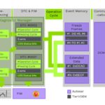
Diagram showing connections between the CAN breakout box, vehicle CAN bus, ECOM interface, and diagnostic software.
Alt text: Diagram illustrating the setup of a CAN breakout box connected to a vehicle’s CAN bus, an ECOM interface, and diagnostic software, highlighting the connections for effective signal monitoring and diagnostics.
Screenshot of oscilloscope displaying CAN bus signals, highlighting voltage levels and timing.
Alt text: Screenshot from an oscilloscope displaying real-time CAN bus signals, emphasizing the voltage levels and precise timing crucial for diagnosing communication issues in a vehicle’s network.
Screenshot of diagnostic software interface showing ECU data and error codes.
Alt text: Screenshot of diagnostic software interface displaying comprehensive ECU data and error codes, showcasing the software’s role in vehicle diagnostics and troubleshooting.
5. Key Considerations When Using ECOM and CAN Breakout Boxes
When using ECOM and CAN breakout boxes, several key considerations can ensure accurate and safe diagnostics.
5.1. Voltage Levels
Ensuring that the voltage levels are correct is crucial for proper CAN bus communication. According to Bosch’s CAN specification, the standard voltage levels are typically around 2.5V for recessive bits and either 0V or 5V for dominant bits, depending on the system. Monitoring these voltage levels with an oscilloscope connected to the CAN breakout box can help identify issues such as voltage drops, signal reflections, or termination problems.
5.2. Signal Timing
Accurate signal timing is essential for reliable data transmission on the CAN bus. Deviations from the expected timing can indicate synchronization issues, clock drift, or communication errors. Using an oscilloscope, technicians can measure the pulse width, bit rate, and inter-frame spacing to verify that the CAN bus signals meet the specified timing requirements.
5.3. Termination Resistors
Proper termination is necessary to prevent signal reflections and ensure signal integrity on the CAN bus. The CAN bus typically requires a 120-ohm termination resistor at each end of the bus. Verifying the presence and correct value of these termination resistors with a multimeter is crucial for diagnosing communication issues.
5.4. Software Compatibility
Ensuring that the diagnostic software is compatible with the ECOM interface and the vehicle’s ECUs is essential for proper communication and data analysis. Incompatibilities can lead to communication errors, incorrect data readings, or even damage to the ECUs. Always check the software’s compatibility list and update to the latest version to avoid potential issues.
5.5. Safety Precautions
When working with electrical systems in vehicles, it is important to follow proper safety precautions to prevent injury or damage to equipment. Always disconnect the vehicle’s battery before working on the CAN bus or ECUs, and use insulated tools to avoid short circuits. Additionally, be cautious when probing the CAN bus signals with an oscilloscope or multimeter to prevent accidental grounding or shorting of the signals.
6. Common Problems and Solutions When Using ECOM and CAN Breakout Boxes
Even with the best equipment, you might encounter some common issues when using ECOM and CAN breakout boxes. Here are some problems and their solutions.
6.1. Communication Errors
- Problem: The ECOM interface fails to establish a connection with the vehicle’s ECUs.
- Solution:
- Verify that the ECOM interface is properly connected to the vehicle’s OBD-II port and to your computer.
- Check the diagnostic software settings to ensure that the correct communication protocol and baud rate are selected.
- Update the ECOM interface firmware and diagnostic software to the latest versions.
- Inspect the OBD-II port for any damage or corrosion that may be preventing proper communication.
- Try a different vehicle to rule out any issues with the ECOM interface or software.
6.2. Signal Distortion
- Problem: The CAN bus signals displayed on the oscilloscope are distorted or noisy, making it difficult to analyze the data.
- Solution:
- Check the CAN bus wiring for any damage, corrosion, or loose connections that may be causing signal interference.
- Verify that the termination resistors are properly installed and have the correct value (120 ohms).
- Use shielded cables and connectors to minimize electromagnetic interference (EMI).
- Ensure that the oscilloscope is properly grounded to the vehicle’s chassis to reduce noise.
- Adjust the oscilloscope settings, such as the voltage scale and time base, to optimize the signal display.
6.3. Inaccurate Readings
- Problem: The voltage levels or timing measurements on the CAN bus do not match the expected values.
- Solution:
- Calibrate the oscilloscope and multimeter to ensure accurate readings.
- Verify that the measuring probes are properly connected to the CAN breakout box and making good contact with the test points.
- Check the vehicle’s wiring diagrams to confirm the expected voltage levels and signal timing for the CAN bus.
- Inspect the CAN bus transceivers in the ECUs for any signs of damage or malfunction.
- Replace any faulty components, such as wiring, connectors, or transceivers, as needed.
6.4. Software Incompatibility
- Problem: The diagnostic software is not compatible with the ECOM interface or the vehicle’s ECUs.
- Solution:
- Check the software’s compatibility list to ensure that it supports the ECOM interface and the vehicle’s make and model.
- Update the diagnostic software to the latest version, which may include compatibility improvements and bug fixes.
- Contact the software vendor for technical support and assistance with compatibility issues.
- Try a different diagnostic software that is known to be compatible with the ECOM interface and the vehicle’s ECUs.
6.5. Power Supply Issues
- Problem: The ECOM interface or CAN breakout box is not receiving enough power, causing it to malfunction or fail to operate.
- Solution:
- Verify that the vehicle’s battery is fully charged and providing sufficient voltage (typically 12V).
- Check the power supply connections to the ECOM interface and CAN breakout box to ensure they are secure and making good contact.
- Use a separate power supply or battery to power the ECOM interface and CAN breakout box, if necessary.
- Inspect the vehicle’s wiring and fuses for any damage or blown fuses that may be preventing power from reaching the diagnostic equipment.
7. Advanced Techniques for Signal Monitoring with ECOM and CAN Breakout Boxes
Beyond basic diagnostics, ECOM and CAN breakout boxes can be used for advanced signal monitoring techniques.
7.1. J1939 Monitoring
J1939 is a communication protocol commonly used in heavy-duty vehicles, such as trucks and buses. Monitoring J1939 signals with ECOM and a CAN breakout box allows technicians to diagnose issues related to the engine, transmission, braking system, and other critical components.
7.1.1. How to Monitor J1939 Signals
- Connect the Equipment: Connect the CAN breakout box to the vehicle’s J1939 diagnostic port (typically a 9-pin Deutsch connector) and the ECOM interface to the same port.
- Configure the Software: Configure the diagnostic software to communicate using the J1939 protocol and select the appropriate parameter groups (PGs) and suspect parameter numbers (SPNs) to monitor.
- Monitor the Signals: Use the oscilloscope to monitor the CAN bus signals, paying attention to the voltage levels, timing, and data being transmitted.
- Analyze the Data: Analyze the data from the ECUs using ECOM and correlate it with the physical signals monitored by the CAN breakout box to identify any issues.
7.1.2. Example Scenario
Suppose you are diagnosing a problem with the engine’s fuel injection system in a heavy-duty truck. By monitoring the J1939 signals related to fuel pressure, injection timing, and injector pulse width, you can identify any anomalies that may be causing the issue. If the fuel pressure is too low or the injection timing is incorrect, you can use ECOM to further diagnose the engine control module (ECM) and identify any fault codes or calibration issues.
7.2. LIN Bus Monitoring
LIN (Local Interconnect Network) is a communication protocol commonly used for low-speed communication in vehicles, such as controlling power windows, door locks, and lighting. Monitoring LIN bus signals with ECOM and a CAN breakout box allows technicians to diagnose issues related to these systems.
7.2.1. How to Monitor LIN Bus Signals
- Connect the Equipment: Connect the CAN breakout box to the vehicle’s LIN bus diagnostic port (typically located near the component being monitored) and the ECOM interface to the OBD-II port.
- Configure the Software: Configure the diagnostic software to communicate using the LIN protocol and select the appropriate data frames to monitor.
- Monitor the Signals: Use the oscilloscope to monitor the LIN bus signals, paying attention to the voltage levels, timing, and data being transmitted.
- Analyze the Data: Analyze the data from the ECUs using ECOM and correlate it with the physical signals monitored by the CAN breakout box to identify any issues.
7.2.2. Example Scenario
Suppose you are diagnosing a problem with the power windows in a vehicle. By monitoring the LIN bus signals related to the window switches and the window motor, you can identify any anomalies that may be causing the issue. If the window switch signals are not being transmitted properly or the window motor is not receiving the correct commands, you can use ECOM to further diagnose the body control module (BCM) and identify any fault codes or configuration issues.
7.3. FlexRay Monitoring
FlexRay is a high-speed communication protocol used in some advanced vehicles for critical systems such as steering, braking, and suspension. Monitoring FlexRay signals with ECOM and a CAN breakout box allows technicians to diagnose complex issues related to these systems.
7.3.1. How to Monitor FlexRay Signals
- Connect the Equipment: Connect the CAN breakout box to the vehicle’s FlexRay diagnostic port (typically located near the component being monitored) and the ECOM interface to the OBD-II port.
- Configure the Software: Configure the diagnostic software to communicate using the FlexRay protocol and select the appropriate communication cycles and data frames to monitor.
- Monitor the Signals: Use a high-speed oscilloscope to monitor the FlexRay signals, paying attention to the voltage levels, timing, and data being transmitted.
- Analyze the Data: Analyze the data from the ECUs using ECOM and correlate it with the physical signals monitored by the CAN breakout box to identify any issues.
7.3.2. Example Scenario
Suppose you are diagnosing a problem with the adaptive cruise control system in a vehicle. By monitoring the FlexRay signals related to the radar sensors, braking system, and engine control, you can identify any anomalies that may be causing the issue. If the radar signals are not being processed correctly or the braking system is not responding properly, you can use ECOM to further diagnose the संबंधित ECUs and identify any fault codes or calibration issues.
8. Training and Resources for ECOM and CAN Breakout Box Usage
Proper training is essential for technicians to effectively use ECOM and CAN breakout boxes. DTS-MONACO.EDU.VN offers comprehensive training and resources to help technicians master these tools.
8.1. DTS-MONACO.EDU.VN Training Programs
DTS-MONACO.EDU.VN provides specialized training programs focusing on ECOM, CAN breakout boxes, and advanced diagnostic techniques. These programs are designed to equip technicians with the knowledge and skills needed to diagnose and repair modern vehicles efficiently.
8.1.1. Course Curriculum
The training programs cover a range of topics, including:
- Introduction to CAN Bus: Understanding the basics of the Controller Area Network and its role in vehicle communication.
- ECOM Interface: Learning how to use the ECOM interface for ECU programming, diagnostics, and data logging.
- CAN Breakout Box: Mastering the use of CAN breakout boxes for physical signal monitoring and fault isolation.
- Signal Analysis: Analyzing CAN bus signals with oscilloscopes and multimeters to identify communication issues.
- Advanced Protocols: Exploring advanced communication protocols such as J1939, LIN, and FlexRay.
- Troubleshooting: Diagnosing and troubleshooting common issues related to CAN bus communication.
- Hands-On Training: Practical exercises and real-world case studies to reinforce learning.
8.1.2. Benefits of Training with DTS-MONACO.EDU.VN
- Expert Instructors: Learn from experienced instructors with in-depth knowledge of automotive diagnostics and communication systems.
- Comprehensive Curriculum: Receive comprehensive training covering all aspects of ECOM and CAN breakout box usage.
- Hands-On Experience: Gain practical experience through hands-on exercises and real-world case studies.
- Certification: Earn a certification upon completion of the training program to demonstrate your expertise.
- Career Advancement: Enhance your skills and career prospects by becoming proficient in advanced diagnostic techniques.
8.2. Online Resources and Documentation
DTS-MONACO.EDU.VN also provides a variety of online resources and documentation to support technicians in their diagnostic efforts.
8.2.1. Technical Articles
Access a library of technical articles covering various topics related to ECOM, CAN breakout boxes, and automotive diagnostics. These articles provide valuable insights and practical tips for troubleshooting common issues and performing advanced procedures.
8.2.2. User Manuals
Download user manuals for ECOM interfaces, CAN breakout boxes, and diagnostic software to learn how to properly use the equipment and software.
8.2.3. Video Tutorials
Watch video tutorials demonstrating how to perform specific diagnostic procedures using ECOM and CAN breakout boxes. These tutorials provide step-by-step instructions and visual aids to help technicians learn more effectively.
8.2.4. Forum and Community Support
Participate in online forums and communities to connect with other technicians, share knowledge, and ask questions related to ECOM, CAN breakout boxes, and automotive diagnostics.
8.3. Industry Certifications
Earning industry certifications can demonstrate your expertise and enhance your career prospects. Some relevant certifications include:
- ASE Certifications: Automotive Service Excellence (ASE) certifications in electrical/electronic systems, engine performance, and advanced engine performance.
- OEM Certifications: Certifications offered by original equipment manufacturers (OEMs) for specific vehicle makes and models.
- Industry-Specific Training: Completing training courses offered by industry organizations and equipment manufacturers.
9. Future Trends in Automotive Diagnostics and Signal Monitoring
The field of automotive diagnostics is constantly evolving, with new technologies and techniques emerging to address the increasing complexity of modern vehicles.
9.1. Increased Use of Wireless Communication
Wireless communication technologies, such as Wi-Fi, Bluetooth, and cellular, are becoming increasingly prevalent in automotive diagnostics. Wireless ECOM interfaces and CAN breakout boxes allow technicians to perform diagnostic procedures remotely, without the need for physical connections. This can improve efficiency and convenience, especially when working on vehicles in remote locations or difficult-to-access areas.
9.2. Integration of Artificial Intelligence (AI)
AI is being integrated into diagnostic software to automate the diagnostic process and provide technicians with more accurate and timely information. AI-powered diagnostic tools can analyze data from multiple sources, identify patterns, and suggest potential causes of problems. This can help technicians troubleshoot issues more quickly and effectively.
9.3. Enhanced Data Analytics
Data analytics is playing an increasingly important role in automotive diagnostics. By collecting and analyzing data from vehicles over time, manufacturers and service providers can identify trends, predict failures, and improve the design and performance of vehicles. Enhanced data analytics can also help technicians diagnose issues more accurately by comparing the vehicle’s data to historical data from other vehicles.
9.4. Cybersecurity Measures
As vehicles become more connected, cybersecurity is becoming a growing concern. Diagnostic tools and procedures must incorporate security measures to protect vehicles from cyberattacks. This includes secure communication protocols, authentication mechanisms, and intrusion detection systems.
9.5. Remote Diagnostics and Over-the-Air (OTA) Updates
Remote diagnostics and OTA updates are becoming more common, allowing technicians to diagnose and repair vehicles remotely and update software without the need for physical access. This can improve efficiency and convenience, especially for fleet operators and owners of electric vehicles.
10. FAQ about ECOM and CAN Breakout Boxes
10.1. What is ECOM?
ECOM is a communication interface used for diagnosing and programming electronic control units (ECUs) in vehicles.
10.2. What is a CAN breakout box?
A CAN breakout box is a diagnostic tool used to physically access and monitor signals on a Controller Area Network (CAN) bus.
10.3. Can ECOM be used with a CAN breakout box?
Yes, ECOM can be used with CAN breakout boxes for enhanced diagnostics and signal monitoring.
10.4. How do I set up ECOM with a CAN breakout box?
Connect the CAN breakout box to the vehicle’s CAN bus and the ECOM interface to the OBD-II port, then configure the diagnostic software and monitoring devices.
10.5. What are the key considerations when using ECOM and CAN breakout boxes?
Key considerations include voltage levels, signal timing, termination resistors, software compatibility, and safety precautions.
10.6. What are some common problems when using ECOM and CAN breakout boxes?
Common problems include communication errors, signal distortion, inaccurate readings, software incompatibility, and power supply issues.
10.7. What are some advanced techniques for signal monitoring with ECOM and CAN breakout boxes?
Advanced techniques include J1939 monitoring, LIN bus monitoring, and FlexRay monitoring.
10.8. Where can I find training and resources for ECOM and CAN breakout box usage?
DTS-MONACO.EDU.VN offers comprehensive training programs and resources for ECOM and CAN breakout box usage.
10.9. What are some future trends in automotive diagnostics and signal monitoring?
Future trends include increased use of wireless communication, integration of artificial intelligence (AI), enhanced data analytics, cybersecurity measures, and remote diagnostics and over-the-air (OTA) updates.
10.10. How can DTS-MONACO.EDU.VN help me with car coding and automotive diagnostics?
DTS-MONACO.EDU.VN provides in-depth training, resources, and support for car coding, advanced diagnostics, and using tools like ECOM and CAN breakout boxes to enhance your skills and career.
In conclusion, the synergy between ECOM and CAN breakout boxes provides an effective solution for modern automotive diagnostics, enabling technicians to pinpoint issues with greater accuracy and efficiency. By leveraging the resources and training available at DTS-MONACO.EDU.VN, you can enhance your skills, stay updated with the latest technologies, and ensure you’re equipped to tackle the challenges of today’s automotive landscape.
Ready to take your automotive diagnostic skills to the next level? Visit DTS-MONACO.EDU.VN today to explore our comprehensive training programs, software solutions, and expert support. Contact us at Whatsapp: +1 (641) 206-8880 or visit our location at 275 N Harrison St, Chandler, AZ 85225, United States. Let us help you master car coding and advanced diagnostics with DTS-MONACO!