Are you troubleshooting a MOST (Media Oriented Systems Transport) ring issue in a vehicle and wondering if a standard diagnostic tool can pinpoint the break? The answer is no; C4/C6 or other similar tools can’t accurately identify the location of a break in the MOST ring, specialized MOST testers are required. At DTS-MONACO.EDU.VN, we provide the resources you need to diagnose and resolve complex automotive issues, including in-depth knowledge and training on specialized tools and car coding. Explore advanced vehicle diagnostics and car coding solutions to optimize your repair skills.
Contents
- 1. What is the MOST Ring and Why is it Important?
- 2. Why Can’t C4/C6 Directly Pinpoint a Break in the MOST Ring?
- 3. The Role of Specialized MOST Testers
- 3.1 Optical Signal Analysis
- 3.2 Continuity Testing
- 3.3 Error Localization
- 4. Common Issues in MOST Ring Networks
- 4.1 Fiber Optic Cable Damage
- 4.2 Connector Problems
- 4.3 Component Failure
- 4.4 Software and Configuration Errors
- 4.5 Loop Breakage
- 5. Step-by-Step Guide to Diagnosing a MOST Ring Break
- 5.1 Preliminary Checks
- 5.2 Using a MOST Tester
- 5.3 Isolating the Faulty Component
- 5.4 Verifying the Repair
- 5.5 Documentation
- 6. Advanced Diagnostic Techniques
- 6.1 Signal Injection
- 6.2 Loopback Testing
- 6.3 Jitter Analysis
- 6.4 Eye Pattern Analysis
- 6.5 Software Diagnostics
- 7. Preventive Maintenance for MOST Ring Networks
- 7.1 Regular Inspections
- 7.2 Connector Cleaning
- 7.3 Cable Management
- 7.4 Firmware Updates
- 7.5 System Diagnostics
- 8. Choosing the Right MOST Tester
- 8.1 Compatibility
- 8.2 Functionality
- 8.3 Ease of Use
- 8.4 Reliability
- 8.5 Cost
1. What is the MOST Ring and Why is it Important?
The Media Oriented Systems Transport (MOST) ring is a high-speed multimedia network used in modern vehicles to transmit audio, video, and control data between various components. It is crucial for operating entertainment, navigation, and advanced driver-assistance systems (ADAS). Understanding the MOST ring’s functionality is the first step in diagnosing issues accurately.
The MOST (Media Oriented Systems Transport) ring serves as the backbone for multimedia communication within a vehicle, enabling the seamless transfer of audio, video, and control data between various components. Here’s a breakdown:
- High-Speed Data Transmission: The MOST ring is designed to handle high bandwidth requirements, ensuring smooth and real-time delivery of multimedia content.
- Component Interconnectivity: It connects essential systems such as the head unit, amplifier, navigation system, display screens, and advanced driver-assistance systems (ADAS).
- Fiber Optic Technology: Utilizes fiber optic cables for data transmission, offering immunity to electromagnetic interference and ensuring data integrity.
- Data Types: Supports various data types, including audio streams (e.g., music, voice), video feeds (e.g., navigation maps, rear-view camera), and control signals (e.g., volume adjustment, system settings).
- Network Topology: Typically configured in a ring topology, where data travels in a circular path, allowing each component to receive and transmit data efficiently.
The MOST ring is not just a luxury feature; it’s integral to the functionality of modern vehicles. Its reliable data transmission is essential for a wide range of systems.
- Entertainment: High-quality audio and video playback for an immersive entertainment experience.
- Navigation: Real-time map data and guidance for precise navigation.
- Driver Assistance: Data from sensors and cameras for ADAS features like lane departure warning, adaptive cruise control, and parking assistance.
- Diagnostics: Diagnostic data transfer for vehicle health monitoring and troubleshooting.
- Communication: Enables communication between various vehicle modules, ensuring synchronized operation and data sharing.
2. Why Can’t C4/C6 Directly Pinpoint a Break in the MOST Ring?
While C4/C6 diagnostic tools are powerful for overall system diagnostics, they lack the specialized hardware and software needed to analyze MOST ring signal integrity. They can indicate a fault within the MOST network but cannot pinpoint the exact location of the break. This is where dedicated MOST testers come in.
C4/C6 diagnostic tools are valuable for comprehensive vehicle diagnostics, they are not equipped to directly identify the precise location of a break in the MOST ring due to their inherent limitations.
- General Diagnostic Focus: C4/C6 tools are designed for broad system diagnostics, covering a wide range of vehicle modules and functions, but they lack the specificity required for detailed MOST ring analysis.
- Software Limitations: The software in C4/C6 tools is not tailored to analyze the complex optical signals and data packets transmitted within the MOST ring.
- Hardware Incompatibility: Standard C4/C6 interfaces do not include the necessary hardware components to interface directly with the fiber optic cables used in MOST networks.
- Data Interpretation: While C4/C6 tools can report a fault within the MOST network, they cannot provide granular data about the signal strength, continuity, or error location within the ring.
- Signal Integrity Analysis: C4/C6 tools do not perform advanced signal integrity analysis, which is essential for identifying disruptions or breaks in the optical signal path.
Specialized MOST testers are crucial for pinpointing breaks in the MOST ring. These testers offer functionalities that C4/C6 tools lack, making them indispensable for accurate diagnostics.
- Optical Signal Analysis: MOST testers can analyze the optical signal strength and quality at various points in the ring, identifying areas with signal degradation or complete loss.
- Continuity Testing: These testers can perform continuity tests on the fiber optic cables to ensure they are intact and properly connected.
- Error Localization: MOST testers can pinpoint the exact location of a break or fault by injecting test signals and monitoring their propagation around the ring.
- Component-Level Diagnostics: Some advanced MOST testers can diagnose issues within individual components connected to the MOST ring, such as amplifiers or head units.
- Real-Time Monitoring: MOST testers provide real-time monitoring of data transmission, allowing technicians to observe network behavior and identify intermittent issues.
3. The Role of Specialized MOST Testers
Specialized MOST testers are designed with the specific hardware and software necessary to analyze the optical signals and data packets within the MOST ring. These tools can perform tests such as optical signal analysis, continuity testing, and error localization. Here’s a closer look:
3.1 Optical Signal Analysis
MOST testers measure the strength and quality of the optical signal at various points in the ring. This helps identify areas where the signal is weak or degraded, indicating a potential break or faulty component.
- Signal Strength Measurement: MOST testers use optical power meters to measure the intensity of the optical signal at different points in the MOST ring. Low signal strength indicates signal loss due to damaged cables, poor connections, or faulty components.
- Signal Quality Analysis: In addition to signal strength, MOST testers can analyze the quality of the optical signal by measuring parameters such as jitter, bit error rate (BER), and optical return loss (ORL). High jitter or BER indicates signal distortion, which can lead to communication errors and system malfunctions.
- Wavelength Verification: MOST testers can verify the wavelength of the optical signal to ensure it matches the specifications of the MOST standard. Incorrect wavelength can result in signal degradation and incompatibility issues.
- Real-Time Monitoring: MOST testers provide real-time monitoring of optical signal parameters, allowing technicians to observe signal behavior and identify intermittent issues.
3.2 Continuity Testing
These testers can perform continuity tests on the fiber optic cables to ensure they are intact and properly connected. A break in the cable or a loose connection will result in a failed continuity test.
- Optical Time Domain Reflectometry (OTDR): OTDR is a technique used to detect faults, breaks, and other anomalies in fiber optic cables. It works by sending a pulse of light into the cable and analyzing the reflected signal. The reflected signal provides information about the location and severity of any faults.
- Visual Fault Locator (VFL): VFL is a simple and cost-effective tool for identifying breaks and bends in fiber optic cables. It works by injecting a visible red light into the cable. The light will escape at the point of a break or bend, allowing technicians to visually locate the fault.
- End-to-End Continuity Testing: MOST testers can perform end-to-end continuity tests by sending a test signal from one end of the fiber optic cable to the other. If the signal is received at the other end, it indicates that the cable is intact and properly connected.
3.3 Error Localization
By injecting test signals into the MOST ring and monitoring their propagation, specialized testers can pinpoint the exact location of a break or fault. This is crucial for efficient repairs.
- Time Domain Reflectometry (TDR): TDR is a technique used to locate faults and breaks in electrical cables. It works by sending a pulse of electrical energy into the cable and analyzing the reflected signal. The reflected signal provides information about the location and nature of any faults.
- Frequency Domain Reflectometry (FDR): FDR is a technique used to locate faults and breaks in coaxial cables. It works by sending a swept frequency signal into the cable and analyzing the reflected signal. The reflected signal provides information about the location and impedance of any faults.
- Signal Tracing: MOST testers can use signal tracing techniques to follow the path of a test signal as it propagates around the MOST ring. By monitoring the signal strength and quality at various points, technicians can identify the location where the signal is lost or degraded.
- Loopback Testing: MOST testers can perform loopback tests by sending a test signal from one port to another on the same device. If the signal is received correctly, it indicates that the device is functioning properly.
4. Common Issues in MOST Ring Networks
Understanding common issues in MOST ring networks can help technicians efficiently diagnose and repair problems. Here are some of the most frequent issues encountered.
4.1 Fiber Optic Cable Damage
Fiber optic cables are susceptible to damage from bending, crushing, or exposure to extreme temperatures. Damaged cables can cause signal loss or complete network failure.
- Bending: Excessive bending of fiber optic cables can cause them to crack or break, resulting in signal loss.
- Crushing: Fiber optic cables can be crushed by heavy objects or pinched in tight spaces, leading to damage and signal degradation.
- Temperature Extremes: Extreme temperatures can cause fiber optic cables to expand or contract, leading to stress and potential damage.
- Moisture Ingress: Moisture can penetrate the protective layers of fiber optic cables, causing corrosion and signal loss.
4.2 Connector Problems
Loose or corroded connectors can disrupt the optical signal path, causing intermittent or complete network failure. Proper connector maintenance is essential for reliable operation.
- Loose Connections: Loose connectors can cause signal loss or intermittent connectivity issues.
- Corrosion: Corrosion on connector surfaces can impede the transmission of optical signals, leading to signal degradation.
- Contamination: Dust, dirt, and other contaminants can accumulate on connector surfaces, blocking the optical signal path and causing signal loss.
- Mismatched Connectors: Using mismatched connectors can cause improper alignment and signal loss.
4.3 Component Failure
Individual components within the MOST ring, such as amplifiers, head units, or navigation systems, can fail, disrupting the entire network. Isolating the faulty component is crucial for effective repair.
- Power Supply Issues: Components may fail due to power supply problems, such as voltage fluctuations or power surges.
- Internal Damage: Internal components within devices can be damaged by heat, vibration, or electrical stress.
- Software Glitches: Software glitches or firmware errors can cause devices to malfunction and disrupt network communication.
- Overheating: Overheating can cause components to fail prematurely, especially in enclosed spaces with poor ventilation.
4.4 Software and Configuration Errors
Incorrect software settings or configuration errors can prevent proper communication between devices in the MOST ring. Verifying and correcting these settings is essential.
- Incorrect Device Addressing: Devices may be assigned incorrect addresses, preventing them from communicating with other devices on the network.
- Firmware Incompatibilities: Using incompatible firmware versions on different devices can cause communication errors and system instability.
- Configuration Conflicts: Configuration conflicts between devices can lead to communication problems and system malfunctions.
- Software Bugs: Software bugs or errors can cause devices to behave unpredictably and disrupt network communication.
4.5 Loop Breakage
A loop breakage occurs when the MOST ring is interrupted, causing a break in the data transmission pathway. This can result from cable damage, connector issues, or component failures.
- Physical Damage: Physical damage to fiber optic cables or connectors can cause a break in the loop, interrupting data transmission.
- Component Failures: Failures of devices within the loop can break the data transmission pathway, causing a loop breakage.
- Misconfigured Devices: Misconfigured devices can disrupt the loop by failing to properly forward data to the next device in the ring.
- Software Issues: Software issues or glitches can cause devices to stop transmitting data, leading to a loop breakage.
5. Step-by-Step Guide to Diagnosing a MOST Ring Break
Diagnosing a break in a MOST ring requires a systematic approach. Here’s a step-by-step guide to help you identify and resolve the issue.
5.1 Preliminary Checks
Before using specialized tools, perform a visual inspection of all MOST ring components and connections. Look for any obvious signs of damage or loose connections.
- Visual Inspection: Visually inspect all fiber optic cables for signs of damage, such as cracks, bends, or cuts. Check connectors for looseness, corrosion, or contamination.
- Power Check: Verify that all components in the MOST ring are receiving power and are turned on.
- Connector Check: Ensure that all fiber optic connectors are securely plugged into their respective devices and that they are properly aligned.
- Device Status: Check the status indicators on each device to see if any are reporting errors or failures.
5.2 Using a MOST Tester
Connect the MOST tester to various points in the ring to measure optical signal strength and perform continuity tests. Follow the tester’s instructions for accurate readings.
- Signal Strength Measurement: Use the MOST tester to measure the optical signal strength at different points in the MOST ring. Compare the readings to the manufacturer’s specifications to identify areas of signal loss.
- Continuity Testing: Perform continuity tests on the fiber optic cables to ensure they are intact and properly connected.
- Loopback Testing: Perform loopback tests on individual devices to verify their functionality and identify any internal issues.
- Error Localization: Use the MOST tester to inject test signals into the ring and monitor their propagation to pinpoint the location of a break or fault.
5.3 Isolating the Faulty Component
Once you’ve identified a section of the MOST ring with a weak or missing signal, isolate the components in that section to determine which one is faulty.
- Component Isolation: Disconnect each component in the suspect section of the MOST ring and test them individually to identify the faulty device.
- Bypass Testing: Use bypass connectors to temporarily bypass individual devices and see if the MOST ring returns to normal operation.
- Substitution Testing: Replace suspect components with known good units to see if the issue is resolved.
- Visual Inspection: Perform a thorough visual inspection of each component for signs of damage, such as burnt components or broken connectors.
5.4 Verifying the Repair
After replacing or repairing the faulty component, use the MOST tester to verify that the signal strength and continuity are restored to normal levels.
- Signal Strength Verification: Use the MOST tester to measure the optical signal strength at various points in the repaired section of the MOST ring.
- Continuity Verification: Perform continuity tests on the fiber optic cables to ensure they are intact and properly connected.
- System Testing: Test the overall functionality of the MOST ring by verifying that all devices are communicating properly and that all multimedia functions are working as expected.
- Error Code Clearing: Clear any error codes that may have been stored in the vehicle’s diagnostic system as a result of the MOST ring issue.
5.5 Documentation
Document all diagnostic steps, test results, and repairs performed. This information can be valuable for future troubleshooting and maintenance.
- Diagnostic Log: Maintain a diagnostic log that records all test results, measurements, and observations made during the diagnostic process.
- Repair Records: Keep detailed records of all repairs performed, including the parts replaced, the procedures followed, and the dates of service.
- Component History: Track the history of each component in the MOST ring, including their installation dates, maintenance records, and any previous repairs.
- System Diagrams: Maintain up-to-date system diagrams of the MOST ring, showing the location of each component and the connections between them.
6. Advanced Diagnostic Techniques
For complex MOST ring issues, advanced diagnostic techniques may be required. These techniques can help identify intermittent faults and subtle signal degradation.
6.1 Signal Injection
Signal injection involves injecting a known signal into the MOST ring and monitoring its behavior as it propagates through the network. This can help identify areas where the signal is being distorted or attenuated.
- Test Signal Generator: Use a test signal generator to inject a known signal into the MOST ring at a specific point.
- Signal Monitoring: Monitor the signal as it propagates through the network using a MOST tester or an oscilloscope.
- Signal Analysis: Analyze the signal for distortion, attenuation, or other anomalies that may indicate a fault.
- Fault Localization: By injecting the signal at different points and monitoring its behavior, technicians can narrow down the location of the fault.
6.2 Loopback Testing
Loopback testing involves sending a test signal from one port on a device to another port on the same device. This can help verify the internal functionality of the device and identify any internal faults.
- Port Configuration: Configure the device to operate in loopback mode, where the output of one port is connected to the input of another port.
- Signal Transmission: Transmit a test signal from the designated output port.
- Signal Reception: Monitor the signal at the designated input port to verify that it is being received correctly.
- Device Verification: If the signal is received correctly, it indicates that the device is functioning properly. If the signal is not received, it indicates an internal fault within the device.
6.3 Jitter Analysis
Jitter analysis involves measuring the timing variations in the optical signal. Excessive jitter can cause communication errors and system malfunctions.
- Jitter Measurement: Use a MOST tester or an oscilloscope to measure the jitter in the optical signal.
- Jitter Comparison: Compare the measured jitter to the manufacturer’s specifications to determine if it is within acceptable limits.
- Fault Identification: Excessive jitter can indicate a fault in the signal source, the transmission path, or the receiving device.
- Corrective Action: Take corrective action to reduce jitter, such as replacing faulty components, improving cable connections, or optimizing device configurations.
6.4 Eye Pattern Analysis
Eye pattern analysis involves displaying the optical signal on an oscilloscope to visualize its quality. A clear and open eye pattern indicates a good signal, while a distorted or closed eye pattern indicates a poor signal.
- Oscilloscope Connection: Connect an oscilloscope to the MOST ring at a point where the optical signal can be accessed.
- Eye Pattern Display: Display the optical signal on the oscilloscope to create an eye pattern.
- Pattern Evaluation: Evaluate the eye pattern for clarity, openness, and symmetry.
- Fault Identification: A distorted or closed eye pattern indicates a fault in the signal source, the transmission path, or the receiving device.
6.5 Software Diagnostics
Advanced diagnostic software can provide detailed information about the status of the MOST ring and its components. This software can monitor data transmission, identify errors, and provide troubleshooting guidance.
- Software Installation: Install the diagnostic software on a compatible computer or diagnostic tool.
- System Connection: Connect the computer or diagnostic tool to the vehicle’s diagnostic port.
- Data Monitoring: Use the software to monitor data transmission, identify errors, and view diagnostic information.
- Troubleshooting Guidance: Follow the software’s troubleshooting guidance to identify and resolve issues in the MOST ring.
7. Preventive Maintenance for MOST Ring Networks
Preventive maintenance is crucial for ensuring the long-term reliability of MOST ring networks. Regular inspections and maintenance can help prevent issues before they occur.
7.1 Regular Inspections
Perform regular visual inspections of all MOST ring components and connections. Look for signs of damage, wear, or corrosion.
- Cable Inspection: Inspect fiber optic cables for signs of damage, such as cracks, bends, or cuts.
- Connector Inspection: Check connectors for looseness, corrosion, or contamination.
- Component Inspection: Inspect components for signs of damage, overheating, or wear.
- Environmental Assessment: Assess the environment around the MOST ring for factors that could contribute to damage or failure, such as exposure to moisture, extreme temperatures, or physical stress.
7.2 Connector Cleaning
Clean fiber optic connectors regularly to remove dust, dirt, and other contaminants that can interfere with the optical signal.
- Cleaning Supplies: Use specialized fiber optic cleaning supplies, such as cleaning wipes and swabs.
- Cleaning Procedure: Follow the manufacturer’s instructions for cleaning fiber optic connectors.
- Inspection After Cleaning: Inspect the connectors after cleaning to ensure that all contaminants have been removed.
- Frequency of Cleaning: Clean fiber optic connectors at regular intervals, depending on the environmental conditions and the frequency of use.
7.3 Cable Management
Proper cable management can help prevent damage to fiber optic cables. Avoid sharp bends and ensure that cables are properly supported and protected.
- Cable Routing: Route fiber optic cables in a way that minimizes bending and stress.
- Cable Support: Use cable supports and ties to secure fiber optic cables and prevent them from sagging or tangling.
- Protection: Protect fiber optic cables from physical damage by using protective sleeves or conduits.
- Strain Relief: Provide strain relief for fiber optic cables at connection points to prevent stress on the connectors.
7.4 Firmware Updates
Keep the firmware on all MOST ring components up to date. Firmware updates can improve performance, fix bugs, and add new features.
- Update Schedule: Establish a schedule for checking and installing firmware updates.
- Compatibility Verification: Verify that the firmware updates are compatible with all components in the MOST ring.
- Installation Procedure: Follow the manufacturer’s instructions for installing firmware updates.
- Testing After Update: Test the MOST ring after installing firmware updates to ensure that all components are functioning properly.
7.5 System Diagnostics
Run regular system diagnostics to identify potential issues before they cause a failure. Use diagnostic software and tools to monitor data transmission, identify errors, and verify component functionality.
- Diagnostic Schedule: Establish a schedule for running system diagnostics.
- Data Monitoring: Monitor data transmission for errors, latency, or other anomalies.
- Error Code Analysis: Analyze error codes to identify potential issues and take corrective action.
- Component Testing: Test individual components to verify their functionality and identify any potential problems.
8. Choosing the Right MOST Tester
Selecting the right MOST tester is essential for efficient and accurate diagnostics. Consider these factors when choosing a MOST tester.
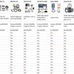
8.1 Compatibility
Ensure that the MOST tester is compatible with the specific MOST standard used in the vehicle you are working on. Different vehicles may use different versions of the MOST standard.
- MOST Standard Support: Verify that the MOST tester supports the MOST standard used in the vehicle.
- Vehicle Coverage: Check the vehicle coverage list to ensure that the MOST tester is compatible with the vehicle’s make, model, and year.
- Interface Compatibility: Ensure that the MOST tester has the necessary interfaces to connect to the vehicle’s diagnostic port and MOST ring components.
- Software Compatibility: Verify that the MOST tester’s software is compatible with the vehicle’s diagnostic system.
8.2 Functionality
Look for a MOST tester that offers a wide range of diagnostic functions, including optical signal analysis, continuity testing, error localization, and component testing.
- Optical Signal Analysis: Ensure that the MOST tester can measure the optical signal strength and quality at various points in the MOST ring.
- Continuity Testing: Verify that the MOST tester can perform continuity tests on the fiber optic cables to ensure they are intact and properly connected.
- Error Localization: Check that the MOST tester can pinpoint the exact location of a break or fault by injecting test signals and monitoring their propagation.
- Component Testing: Ensure that the MOST tester can test individual components, such as amplifiers, head units, and navigation systems.
8.3 Ease of Use
Choose a MOST tester that is easy to use and has a clear and intuitive interface. This will save time and reduce the risk of errors.
- User Interface: Look for a MOST tester with a clear and intuitive user interface.
- Display: Choose a MOST tester with a large, easy-to-read display.
- Documentation: Ensure that the MOST tester comes with comprehensive documentation, including a user manual and troubleshooting guide.
- Training: Consider whether the manufacturer offers training on how to use the MOST tester effectively.
8.4 Reliability
Select a MOST tester from a reputable manufacturer with a proven track record of reliability. A reliable tester will provide accurate results and minimize downtime.
- Manufacturer Reputation: Choose a MOST tester from a reputable manufacturer with a proven track record of reliability.
- Warranty: Check the warranty offered by the manufacturer. A longer warranty indicates that the manufacturer has confidence in the reliability of their product.
- Customer Reviews: Read customer reviews to get an idea of the real-world performance and reliability of the MOST tester.
- Support: Ensure that the manufacturer offers good customer support in case you have any questions or issues.
8.5 Cost
Consider your budget when choosing a MOST tester. While it’s important to invest in a high-quality tester, there are affordable options available that offer