How does the C4 model address communication intricacies in vehicles equipped with multiple CAN gateways? This article dives deep into this question, offering insights into leveraging C4 diagrams alongside tools like PlantUML to visualize and manage complex automotive communication architectures. Discover how DTS-MONACO.EDU.VN can empower you with the knowledge and tools to master car coding and diagnostics. Explore the benefits of structured diagrams, version control, and standardized formats for enhanced collaboration and efficiency in automotive engineering and delve into advanced vehicle diagnostics and car coding techniques to stay ahead in the rapidly evolving automotive industry.
Contents
- 1. Understanding the Challenge of Multiple CAN Gateways in Vehicles
- 1.1 The Role of CAN Gateways
- 1.2 Challenges in Diagnosing Multi-Gateway Systems
- 2. The C4 Model: A Solution for Visualizing Complex Systems
- 2.1 Applying the C4 Model to Vehicle Architecture
- 2.2 Benefits of Using C4 Diagrams for Automotive Systems
- 3. PlantUML: Diagrams as Code for Automotive Architecture
- 3.1 Integrating PlantUML with C4 Model for Automotive Systems
- 3.2 Advantages of Diagrams as Code in Automotive Engineering
- 4. Representing Multiple CAN Gateways with C4 and PlantUML
- 4.1 Creating a System Context Diagram for a Multi-Gateway Vehicle
- 4.2 Designing a Container Diagram for CAN Bus Architecture
- 4.3 Detailing Gateway Internals with Component Diagrams
- 5. Practical Examples: C4 Diagrams for Specific Vehicle Systems
- 5.1 Hybrid Vehicle Powertrain Communication
- 5.2 ADAS System Architecture
- 5.3 Connected Car Services and CAN Gateway Interaction
- 6. Tools and Technologies for Implementing C4 Diagrams in Automotive
- 6.1 Setting Up PlantUML for Automotive Diagramming
- 6.2 Integrating with Version Control Systems
- 6.3 Utilizing Automotive Diagnostic Tools for Validation
- 7. Best Practices for Creating and Maintaining C4 Diagrams in Automotive
- 7.1 Establishing Naming Conventions for Automotive Components
- 7.2 Maintaining Consistency in Diagramming Styles
- 7.3 Keeping Diagrams Up-To-Date with System Changes
- 8. The Future of C4 Diagrams in Automotive Engineering
- 8.1 Impact on Software-Defined Vehicles
- 8.2 Role in Autonomous Driving Systems
- 8.3 Facilitating Over-the-Air Updates
- 9. DTS-MONACO.EDU.VN: Your Partner in Mastering Automotive Diagnostics and Car Coding
- 9.1 Comprehensive Training Programs
- 9.2 Hands-On Experience with DTS-Monaco
- 9.3 Expert Instructors and Cutting-Edge Resources
- 10. Call to Action: Elevate Your Automotive Skills with DTS-MONACO.EDU.VN
- FAQ: C4 Model and Automotive Communication
1. Understanding the Challenge of Multiple CAN Gateways in Vehicles
How do multiple CAN gateways complicate vehicle communication? Modern vehicles increasingly rely on multiple Controller Area Network (CAN) gateways to manage the growing complexity of in-vehicle communication. These gateways act as bridges between different CAN buses, each responsible for specific functions like powertrain, body control, and infotainment. However, this architecture introduces challenges in understanding and managing the overall communication flow.
- Increased Complexity: Multiple CAN buses and gateways create a complex network topology.
- Diagnostic Difficulties: Identifying communication issues across multiple buses can be challenging.
- Security Concerns: Multiple entry points increase the risk of unauthorized access.
- Software Updates: Managing software updates across different ECUs and buses requires careful coordination.
1.1 The Role of CAN Gateways
What is the primary function of CAN gateways in automotive networks? CAN gateways facilitate communication between different CAN buses within a vehicle. They translate messages between buses with varying speeds and protocols, ensuring seamless data exchange between different electronic control units (ECUs). According to the Society of Automotive Engineers (SAE), modern vehicles can have more than 70 ECUs communicating over multiple CAN buses, highlighting the necessity for efficient gateway management.
1.2 Challenges in Diagnosing Multi-Gateway Systems
What are the key challenges in diagnosing vehicles with multiple CAN gateways? Diagnosing issues in multi-gateway systems requires a comprehensive understanding of the network architecture. Technicians need to trace communication paths across different buses, identify faulty ECUs, and resolve conflicts between different systems. As highlighted in a technical paper by Bosch, effective diagnostics requires specialized tools and expertise to analyze CAN bus traffic and identify anomalies.
2. The C4 Model: A Solution for Visualizing Complex Systems
How does the C4 model simplify the visualization of complex vehicle communication systems? The C4 model offers a hierarchical approach to visualizing software architecture, breaking down complex systems into four levels of abstraction: Context, Containers, Components, and Code. This approach helps in understanding the system at different levels of detail, making it easier to identify communication paths and potential issues.
- System Context: Shows the vehicle as a whole and its interaction with external systems.
- Container Diagram: Focuses on the major software components within the vehicle, such as the infotainment system, engine control unit (ECU), and body control module (BCM).
- Component Diagram: Zooms into individual components, illustrating their internal structure and interactions.
- Code Diagram: Provides a detailed view of the code-level implementation of specific components.
2.1 Applying the C4 Model to Vehicle Architecture
How can the C4 model be effectively applied to represent the architecture of a vehicle? The C4 model can be applied to vehicle architecture by creating diagrams that represent the system at different levels of detail. For example, a System Context diagram can show the vehicle interacting with external services like cloud platforms and mobile apps. A Container diagram can then zoom into the vehicle, showing the major ECUs and their communication paths.
2.2 Benefits of Using C4 Diagrams for Automotive Systems
What are the advantages of using C4 diagrams for visualizing automotive systems? C4 diagrams provide a clear and structured way to visualize complex automotive systems. They help in understanding the overall architecture, identifying dependencies, and communicating design decisions to different stakeholders. According to a study by the University of Michigan Transportation Research Institute, visual representations like C4 diagrams can significantly improve communication and collaboration in automotive engineering teams.
3. PlantUML: Diagrams as Code for Automotive Architecture
How does PlantUML enable the creation of diagrams as code for automotive architecture? PlantUML is an open-source tool that allows you to create diagrams using a simple text-based language. This approach, known as “diagrams as code,” offers several advantages over traditional diagramming tools, including version control, collaboration, and automation.
- Version Control: Diagrams can be stored in Git repositories, allowing for version tracking and collaboration.
- Automation: Diagrams can be generated automatically from code or configuration files.
- Standardization: PlantUML promotes standardization by providing a consistent way to represent diagrams.
- Integration: PlantUML integrates with various IDEs and build tools, making it easy to incorporate diagrams into the development workflow.
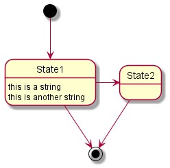 PlantUML Example Diagram
3.1 Integrating PlantUML with C4 Model for Automotive Systems
How can PlantUML be integrated with the C4 model to represent automotive systems effectively? PlantUML can be integrated with the C4 model by using PlantUML’s text-based language to create C4 diagrams. This allows you to define the system context, containers, and components in a structured and version-controlled manner. The C4-PlantUML library provides a set of PlantUML macros that simplify the creation of C4 diagrams.
3.2 Advantages of Diagrams as Code in Automotive Engineering
What are the key benefits of using diagrams as code in the context of automotive engineering? Diagrams as code offers several advantages in automotive engineering, including improved collaboration, version control, and automation. By storing diagrams in Git repositories, engineers can track changes, collaborate on designs, and ensure that diagrams are always up-to-date. According to a survey by IEEE, diagrams as code can reduce documentation time by up to 40% in complex engineering projects.
4. Representing Multiple CAN Gateways with C4 and PlantUML
How can the C4 model and PlantUML be used to effectively represent multiple CAN gateways in a vehicle? To represent multiple CAN gateways with C4 and PlantUML, start with a System Context diagram that shows the vehicle and its interaction with external systems. Then, create a Container diagram that zooms into the vehicle, showing the different CAN buses and gateways as containers. Finally, create Component diagrams that illustrate the internal structure of each gateway and the ECUs connected to each bus.
- System Context Diagram: Shows the vehicle and its interaction with external systems.
- Container Diagram: Shows the different CAN buses and gateways as containers.
- Component Diagram: Illustrates the internal structure of each gateway and the ECUs connected to each bus.
4.1 Creating a System Context Diagram for a Multi-Gateway Vehicle
How do you create a system context diagram for a vehicle with multiple CAN gateways using the C4 model? The System Context diagram should show the vehicle as a single system interacting with external entities such as the driver, cloud services, and diagnostic tools. This diagram provides a high-level overview of the vehicle’s role in the broader ecosystem.
4.2 Designing a Container Diagram for CAN Bus Architecture
What are the key elements to include in a container diagram representing a CAN bus architecture? The Container diagram should illustrate the different CAN buses as containers, with each gateway acting as a bridge between them. This diagram should also show the major ECUs connected to each bus, such as the engine control unit (ECU), body control module (BCM), and infotainment system.
4.3 Detailing Gateway Internals with Component Diagrams
How can component diagrams be used to detail the internal workings of a CAN gateway? Component diagrams can be used to show the internal structure of each CAN gateway, including the communication controllers, routing tables, and security modules. This level of detail is useful for understanding how the gateway processes messages and routes them between different buses.
5. Practical Examples: C4 Diagrams for Specific Vehicle Systems
Can you provide practical examples of C4 diagrams for specific vehicle systems with multiple CAN gateways? Let’s consider a hybrid vehicle with multiple CAN gateways. The System Context diagram would show the vehicle interacting with the driver, charging stations, and cloud services. The Container diagram would show the powertrain CAN bus, the body CAN bus, and the infotainment CAN bus, with gateways connecting them. Component diagrams would then detail the internal structure of each gateway and the ECUs connected to each bus.
- Hybrid Vehicle Powertrain: Illustrates the communication between the engine control unit, battery management system, and electric motor controller.
- Advanced Driver-Assistance Systems (ADAS): Shows the interaction between sensors, cameras, and the central ADAS controller.
- Connected Car Services: Depicts the communication between the vehicle, cloud services, and mobile apps.
5.1 Hybrid Vehicle Powertrain Communication
How can the C4 model visualize the communication flow within a hybrid vehicle’s powertrain system? The C4 model can effectively visualize the communication flow within a hybrid vehicle’s powertrain system by illustrating the interactions between the engine control unit (ECU), battery management system (BMS), and electric motor controller (EMC). This representation helps in understanding the complex data exchange required for efficient hybrid operation.
5.2 ADAS System Architecture
How can C4 diagrams represent the architecture of Advanced Driver-Assistance Systems (ADAS) in a vehicle? C4 diagrams can represent the ADAS architecture by showing the interaction between sensors (e.g., radar, lidar, cameras), the central ADAS controller, and other vehicle systems. This helps in understanding how the ADAS system processes data and makes decisions.
5.3 Connected Car Services and CAN Gateway Interaction
How do C4 diagrams illustrate the interaction between connected car services and CAN gateways? C4 diagrams can illustrate the interaction between connected car services and CAN gateways by showing how data is exchanged between the vehicle, cloud services, and mobile apps. This helps in understanding how the vehicle’s data is used to provide services such as remote diagnostics, over-the-air updates, and infotainment.
6. Tools and Technologies for Implementing C4 Diagrams in Automotive
What tools and technologies are essential for implementing C4 diagrams in the automotive industry? Implementing C4 diagrams in the automotive industry requires a combination of software tools and hardware platforms. PlantUML is the primary tool for creating diagrams as code, while Git is used for version control and collaboration. Additionally, specialized automotive diagnostic tools are needed to analyze CAN bus traffic and validate the accuracy of the diagrams.
- PlantUML: For creating diagrams as code.
- Git: For version control and collaboration.
- Visual Studio Code: For editing PlantUML files with real-time rendering.
- Automotive Diagnostic Tools: For analyzing CAN bus traffic and validating diagrams.
6.1 Setting Up PlantUML for Automotive Diagramming
What are the steps to set up PlantUML for creating automotive diagrams? To set up PlantUML for automotive diagramming, you need to install PlantUML, a text editor or IDE with PlantUML support (e.g., Visual Studio Code with the PlantUML extension), and the C4-PlantUML library. This setup allows you to create C4 diagrams using PlantUML’s text-based language and visualize them in real-time.
6.2 Integrating with Version Control Systems
How can C4 diagrams be integrated with version control systems like Git? C4 diagrams can be integrated with Git by storing the PlantUML files in a Git repository. This allows you to track changes, collaborate on designs, and ensure that diagrams are always up-to-date. You can also use Git hooks to automatically generate diagrams from the PlantUML files whenever changes are committed.
6.3 Utilizing Automotive Diagnostic Tools for Validation
How can automotive diagnostic tools be used to validate the accuracy of C4 diagrams? Automotive diagnostic tools can be used to analyze CAN bus traffic and validate the accuracy of C4 diagrams. By comparing the data flow in the diagrams with the actual data flow on the CAN bus, you can identify discrepancies and ensure that the diagrams accurately represent the system’s behavior.
7. Best Practices for Creating and Maintaining C4 Diagrams in Automotive
What are the best practices for creating and maintaining C4 diagrams in the automotive industry? Creating and maintaining C4 diagrams in the automotive industry requires a structured approach and adherence to best practices. This includes defining clear naming conventions, using consistent diagramming styles, and regularly updating diagrams to reflect changes in the system architecture.
- Define Clear Naming Conventions: Use consistent naming conventions for components and containers.
- Use Consistent Diagramming Styles: Follow the C4 model guidelines for diagramming styles.
- Regularly Update Diagrams: Keep diagrams up-to-date to reflect changes in the system architecture.
- Collaborate with Stakeholders: Involve stakeholders in the diagramming process to ensure accuracy and completeness.
7.1 Establishing Naming Conventions for Automotive Components
Why is it important to establish clear naming conventions for automotive components in C4 diagrams? Establishing clear naming conventions for automotive components helps in maintaining consistency and clarity in C4 diagrams. This makes it easier to understand the diagrams and identify components, especially in complex systems with multiple ECUs and buses.
7.2 Maintaining Consistency in Diagramming Styles
How can consistency in diagramming styles be maintained across different C4 diagrams? Consistency in diagramming styles can be maintained by following the C4 model guidelines and using the C4-PlantUML library. This ensures that all diagrams are created using a consistent set of symbols and conventions, making them easier to understand and interpret.
7.3 Keeping Diagrams Up-To-Date with System Changes
What are the strategies for keeping C4 diagrams up-to-date with changes in the system architecture? To keep C4 diagrams up-to-date, it’s important to integrate them into the development workflow and establish a process for updating them whenever changes are made to the system architecture. This can be achieved by using Git hooks to automatically generate diagrams from the PlantUML files whenever changes are committed.
8. The Future of C4 Diagrams in Automotive Engineering
How do you see the role of C4 diagrams evolving in the future of automotive engineering? The role of C4 diagrams in automotive engineering is expected to grow as vehicles become more complex and software-defined. C4 diagrams will play a crucial role in visualizing and managing the increasing complexity of automotive systems, enabling engineers to design, develop, and maintain these systems more effectively.
- Software-Defined Vehicles: C4 diagrams will be essential for managing the complexity of software-defined vehicles.
- Autonomous Driving Systems: C4 diagrams will help in visualizing the architecture of autonomous driving systems and their interactions with other vehicle systems.
- Over-the-Air Updates: C4 diagrams will aid in managing the deployment and integration of over-the-air updates.
8.1 Impact on Software-Defined Vehicles
How will C4 diagrams impact the development and maintenance of software-defined vehicles? C4 diagrams will have a significant impact on the development and maintenance of software-defined vehicles by providing a clear and structured way to visualize the complex software architecture. This will enable engineers to design, develop, and maintain these systems more effectively, reducing development time and improving reliability.
8.2 Role in Autonomous Driving Systems
How can C4 diagrams assist in understanding the architecture of autonomous driving systems? C4 diagrams can assist in understanding the architecture of autonomous driving systems by visualizing the interactions between sensors, controllers, and other vehicle systems. This helps in identifying dependencies, understanding data flow, and communicating design decisions to different stakeholders.
8.3 Facilitating Over-the-Air Updates
How do C4 diagrams facilitate the management and integration of over-the-air (OTA) updates in vehicles? C4 diagrams facilitate the management and integration of OTA updates by providing a clear understanding of the system architecture and the impact of updates on different components. This helps in planning and executing OTA updates more effectively, reducing the risk of errors and ensuring that updates are deployed smoothly.
9. DTS-MONACO.EDU.VN: Your Partner in Mastering Automotive Diagnostics and Car Coding
How can DTS-MONACO.EDU.VN help you master automotive diagnostics and car coding, especially in the context of complex systems? DTS-MONACO.EDU.VN offers comprehensive training and resources for automotive diagnostics and car coding. Our courses cover a wide range of topics, including CAN bus communication, ECU programming, and advanced diagnostic techniques. We also provide hands-on training with industry-standard tools like DTS-Monaco, helping you develop the skills and knowledge you need to succeed in the automotive industry.
- Comprehensive Training: Courses covering CAN bus communication, ECU programming, and advanced diagnostic techniques.
- Hands-On Experience: Training with industry-standard tools like DTS-Monaco.
- Expert Instructors: Learn from experienced professionals with in-depth knowledge of automotive systems.
- Cutting-Edge Resources: Access to the latest tools and technologies for automotive diagnostics and car coding.
9.1 Comprehensive Training Programs
What types of training programs does DTS-MONACO.EDU.VN offer to enhance skills in automotive diagnostics and car coding? DTS-MONACO.EDU.VN offers a variety of training programs designed to enhance skills in automotive diagnostics and car coding. These programs cover topics such as CAN bus communication, ECU programming, advanced diagnostic techniques, and the use of industry-standard tools like DTS-Monaco.
9.2 Hands-On Experience with DTS-Monaco
How does DTS-MONACO.EDU.VN provide hands-on experience with industry-standard tools like DTS-Monaco? DTS-MONACO.EDU.VN provides hands-on experience with DTS-Monaco through practical exercises and real-world case studies. Students learn how to use DTS-Monaco to diagnose issues, program ECUs, and perform advanced car coding tasks.
9.3 Expert Instructors and Cutting-Edge Resources
Who are the instructors at DTS-MONACO.EDU.VN, and what resources are available for students? DTS-MONACO.EDU.VN instructors are experienced professionals with in-depth knowledge of automotive systems. We provide access to cutting-edge resources, including the latest tools and technologies for automotive diagnostics and car coding.
10. Call to Action: Elevate Your Automotive Skills with DTS-MONACO.EDU.VN
Ready to master automotive diagnostics and car coding? Visit DTS-MONACO.EDU.VN today to explore our comprehensive training programs and resources. Whether you’re a seasoned technician or just starting your career, we have the tools and knowledge you need to succeed. Contact us at [Address: 275 N Harrison St, Chandler, AZ 85225, United States. Whatsapp: +1 (641) 206-8880. Website: DTS-MONACO.EDU.VN] to learn more and start your journey towards becoming an automotive expert.
- Explore Training Programs: Discover our range of courses designed to enhance your skills.
- Contact Us: Reach out to learn more about our offerings and how we can help you succeed.
- Visit Our Website: Access valuable resources and stay up-to-date with the latest industry trends.
Elevate your automotive expertise with DTS-MONACO.EDU.VN and unlock new opportunities in the rapidly evolving automotive industry. Explore advanced car coding techniques, master vehicle diagnostics, and stay ahead with our cutting-edge training and resources.
FAQ: C4 Model and Automotive Communication
Here are some frequently asked questions about using the C4 model for visualizing automotive communication systems:
- What is the C4 model, and how does it apply to automotive engineering?
The C4 model is a hierarchical approach to visualizing software architecture, breaking down complex systems into four levels of abstraction: Context, Containers, Components, and Code. In automotive engineering, it helps in understanding the system at different levels of detail, making it easier to identify communication paths and potential issues. - How can PlantUML be used to create C4 diagrams for vehicles with multiple CAN gateways?
PlantUML is an open-source tool that allows you to create diagrams using a simple text-based language. By integrating PlantUML with the C4 model, you can define the system context, containers, and components in a structured and version-controlled manner. - What are the benefits of using diagrams as code in automotive engineering?
Diagrams as code offers several advantages in automotive engineering, including improved collaboration, version control, and automation. By storing diagrams in Git repositories, engineers can track changes, collaborate on designs, and ensure that diagrams are always up-to-date. - How can automotive diagnostic tools be used to validate the accuracy of C4 diagrams?
Automotive diagnostic tools can be used to analyze CAN bus traffic and validate the accuracy of C4 diagrams. By comparing the data flow in the diagrams with the actual data flow on the CAN bus, you can identify discrepancies and ensure that the diagrams accurately represent the system’s behavior. - What are the best practices for creating and maintaining C4 diagrams in the automotive industry?
Best practices include defining clear naming conventions, using consistent diagramming styles, regularly updating diagrams to reflect changes in the system architecture, and collaborating with stakeholders to ensure accuracy and completeness. - How does DTS-MONACO.EDU.VN support professionals in mastering automotive diagnostics and car coding?
DTS-MONACO.EDU.VN offers comprehensive training and resources for automotive diagnostics and car coding, covering topics such as CAN bus communication, ECU programming, and advanced diagnostic techniques. We also provide hands-on training with industry-standard tools like DTS-Monaco. - What types of training programs are available at DTS-MONACO.EDU.VN?
DTS-MONACO.EDU.VN offers a variety of training programs designed to enhance skills in automotive diagnostics and car coding, including courses on CAN bus communication, ECU programming, advanced diagnostic techniques, and the use of industry-standard tools like DTS-MONACO. - How can C4 diagrams assist in understanding the architecture of autonomous driving systems?
C4 diagrams can assist in understanding the architecture of autonomous driving systems by visualizing the interactions between sensors, controllers, and other vehicle systems. This helps in identifying dependencies, understanding data flow, and communicating design decisions to different stakeholders. - Why is it important to keep C4 diagrams up-to-date with system changes in automotive engineering?
Keeping C4 diagrams up-to-date ensures that they accurately reflect the current state of the system architecture. This is crucial for effective communication, collaboration, and decision-making, especially in complex automotive systems. - How can C4 diagrams facilitate the management and integration of over-the-air (OTA) updates in vehicles?
C4 diagrams facilitate the management and integration of OTA updates by providing a clear understanding of the system architecture and the impact of updates on different components. This helps in planning and executing OTA updates more effectively, reducing the risk of errors and ensuring that updates are deployed smoothly.