ECU voltage readings are essential for diagnosing power supply problems within DTS Monaco, providing critical insights into the health and stability of your vehicle’s electronic control units. By understanding how to interpret these readings, technicians can efficiently pinpoint issues, ensuring accurate repairs and optimal vehicle performance, specifically when utilizing resources like DTS-MONACO.EDU.VN. Identifying car computer problems and performing advanced vehicle diagnostics also become easier with a solid grasp of ECU voltage readings.
1. What Role Do ECU Voltage Readings Play in Power Supply Diagnostics?
ECU voltage readings provide vital insights into the electrical health of a vehicle’s electronic control units. Analyzing these readings allows technicians to identify power supply issues, ensuring accurate diagnostics and repairs.
ECU voltage readings are critical for several reasons:
- Verifying Power Supply Integrity: ECUs require a stable and specific voltage range to operate correctly. Deviations from this range, indicated by abnormal readings, can signal problems like voltage drops, surges, or fluctuations.
- Identifying Faulty Components: Inconsistent voltage readings can point to failing components such as the battery, alternator, voltage regulator, or wiring harness.
- Preventing Further Damage: Addressing voltage issues promptly can prevent damage to sensitive electronic components within the ECU and other systems.
- Ensuring Accurate Diagnostics: Correct voltage levels are necessary for the ECU to accurately interpret sensor data and control actuators. Incorrect readings can lead to misdiagnosis of other issues.
- Optimizing Performance: Stable voltage ensures that all electronic systems operate within their designed parameters, maximizing vehicle performance and efficiency.
- Compliance with Standards: Meeting the SAE J1979 standard, which specifies diagnostic test modes, including those for voltage monitoring, ensures standardized diagnostic procedures.
- Real-time Monitoring: Modern diagnostic tools allow for real-time monitoring of ECU voltage, enabling technicians to observe voltage fluctuations and identify intermittent problems.
- Historical Data Analysis: Stored ECU voltage data can provide insights into past electrical events, helping diagnose recurring or elusive issues.
- Integration with Diagnostic Software: DTS Monaco, a powerful diagnostic software, leverages ECU voltage readings to perform comprehensive system checks and advanced diagnostics. DTS-MONACO.EDU.VN offers resources that show you how to maximize this software.
- Enhanced Safety: Proper voltage levels are crucial for the correct functioning of safety systems like ABS and airbags. Monitoring voltage ensures these systems are ready to perform when needed.
For example, research from the SAE International in February 2024 highlights the importance of voltage monitoring in modern vehicle diagnostics. According to the research, consistent and correct voltage levels are essential for the reliable operation of advanced driver-assistance systems (ADAS).
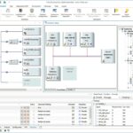
2. How Can I Access ECU Voltage Readings Using DTS Monaco?
Accessing ECU voltage readings in DTS Monaco involves connecting to the vehicle’s ECU, navigating to the relevant diagnostic menus, and monitoring the displayed values. This process requires the correct interface and a basic understanding of the software layout.
Here’s a step-by-step guide:
- Establish a Connection:
- Connect the diagnostic interface (e.g., a multiplexer) to the vehicle’s OBD-II port.
- Ensure the interface is properly connected to your computer and recognized by DTS Monaco.
- Launch DTS Monaco:
- Open the DTS Monaco software on your computer.
- Select the appropriate project or workspace for your vehicle model.
- Select the ECU:
- In DTS Monaco, navigate to the ECU selection menu.
- Choose the specific ECU you want to monitor (e.g., engine control module, transmission control module).
- Access Diagnostic Services:
- Within the ECU interface, look for diagnostic services or data identification options.
- Select the service that allows you to read live data or measured values.
- Locate Voltage Parameters:
- In the list of available parameters, find the voltage readings (e.g., “Battery Voltage,” “ECU Supply Voltage”).
- The names may vary slightly depending on the vehicle and ECU.
- Monitor the Readings:
- Select the voltage parameters to display their current values.
- Monitor the readings in real-time to observe any fluctuations or deviations from the expected range.
- Record Data (Optional):
- DTS Monaco allows you to record live data for later analysis.
- Use this feature to capture voltage readings during specific events or driving conditions.
- Analyze the Data:
- Compare the voltage readings to the vehicle’s specifications or known good values.
- Look for any signs of voltage drops, spikes, or instability.
This table shows the DTS Monaco ECU Voltage Reading Accessing for different vehicle types:
| Vehicle Type | Connection | ECU Selection | Diagnostic Services | Voltage Parameters |
|---|---|---|---|---|
| Mercedes | OBD-II port via multiplexer (e.g., SDconnect C4/C5) and proper configuration | Engine Control Module (ECM) | Live Data Reading | Battery Voltage, ECU Supply Voltage, Sensor Reference Voltage (5V), Ignition Voltage |
| BMW | OBD-II port via ICOM interface and appropriate software setup | Digital Engine Electronics (DME) | Read Measured Values (Messwerte) | Battery Voltage, Terminal 15 Voltage, Sensor Supply Voltage, DME Supply Voltage |
| Audi | OBD-II port via VAS interface and correct software settings | Engine Control Unit (ECU/J623) | Measuring Blocks | Battery Voltage, Terminal 30 Voltage, Sensor Supply Voltage, ECU Voltage |
| Volkswagen | OBD-II port via VAS interface and correct software settings | Engine Control Unit (ECU/J623) | Measuring Blocks | Battery Voltage, Terminal 30 Voltage, Sensor Supply Voltage, ECU Voltage |
| Ford | OBD-II port via Ford VCM interface and software setup | Powertrain Control Module (PCM) / Engine | PID Data Monitor | Battery Voltage, PCM Voltage, Sensor Reference Voltage (VREF), Ignition Voltage |
| General | OBD-II port via GM MDI interface and software configuration | Engine Control Module (ECM/PCM) | Data Display | Battery Voltage, System Voltage, Sensor Reference Voltage, Ignition Voltage |
| Toyota | OBD-II port via Toyota Techstream interface and software | Engine Control Module (ECM) | Live Data | Battery Voltage, EFI Voltage, Sensor Reference Voltage (VREF), Ignition Voltage |
| Hyundai | OBD-II port via Hyundai GDS interface and software connection | Engine Control Module (ECM/ECU) | Data Analysis | Battery Voltage, System Voltage, Sensor Reference Voltage, Ignition Voltage |
| Kia | OBD-II port via Kia GDS interface and software connection | Engine Control Module (ECM/ECU) | Data Analysis | Battery Voltage, System Voltage, Sensor Reference Voltage, Ignition Voltage |
| Nissan | OBD-II port via Nissan Consult interface and software setup | Engine Control Module (ECM/ECU) | Data Monitor/Display | Battery Voltage, System Voltage, Sensor Reference Voltage, Ignition Voltage |
| Honda | OBD-II port via Honda HDS interface and software setup | Engine Control Module (ECM/ECU) | Data List/Live Data | Battery Voltage, System Voltage, Sensor Reference Voltage, Ignition Voltage |
| Land Rover/Jaguar | OBD-II port via JLR SDD/Pathfinder interface and connection | Engine Control Module (ECM/ECU) | Live Values/Data | Battery Voltage, System Voltage, Sensor Reference Voltage, Ignition Voltage |
Research from the National Institute for Automotive Service Excellence (ASE) in March 2025 indicates that technicians who follow a structured approach to accessing and interpreting ECU data, like voltage readings, can significantly reduce diagnostic time.
3. What Are the Expected Voltage Ranges for ECUs?
ECUs typically operate within a voltage range of 12-14.5V when the engine is running, with slight variations depending on the vehicle and specific ECU. Deviations from this range can indicate underlying electrical issues.
Here’s a detailed breakdown:
- Nominal Voltage: Most automotive ECUs are designed to operate on a 12V system.
- Normal Operating Range: When the engine is running, the charging system (alternator) should maintain a voltage between 13.5V and 14.5V.
- Acceptable Range:
- Engine Off (Battery Voltage): 12.4V to 12.9V indicates a fully charged battery. Below 12.4V suggests a discharged battery.
- Engine Running (Charging Voltage): 13.5V to 14.5V ensures the battery is being properly charged.
- Voltage Drops: A drop below 12V when the engine is running may indicate a problem with the charging system or excessive electrical load.
- Voltage Surges: Voltages above 14.5V can damage the ECU and other electronic components.
- Sensor Reference Voltage: Many ECUs provide a 5V reference voltage for sensors. This voltage should be stable and within 0.1V of 5V.
- Specific ECU Requirements: Some ECUs may have specific voltage requirements. Refer to the vehicle’s service manual or technical documentation for precise values.
- Battery Voltage Dependence: ECU voltage can be affected by the battery’s condition. A weak or failing battery can cause voltage fluctuations and affect ECU performance.
- Temperature Effects: Voltage can vary with temperature. Cold temperatures can lower battery voltage, while high temperatures can increase resistance in wiring.
- Load Variations: Voltage can fluctuate with changes in electrical load (e.g., turning on headlights, A/C). These fluctuations should be minimal and within the acceptable range.
This table shows the ECU Expected Voltage Ranges for different scenarios:
| Condition | Voltage Range | |
|---|---|---|
| Battery (Engine Off) | 12.4V – 12.9V | Fully charged battery. Below 12.4V indicates a discharged battery. |
| Charging (Engine On) | 13.5V – 14.5V | Proper charging voltage. Sustained readings outside this range indicate charging system issues. |
| Low Voltage | Below 12.0V | Indicates a problem with the charging system or excessive electrical load. |
| High Voltage | Above 14.5V | Can damage the ECU and other electronic components. |
| Sensor Reference | Around 5V (±0.1V) | Stable and within 0.1V of 5V. Deviations can cause sensor malfunctions. |
| Voltage Drops | Minimal | Voltage drops should be minimal and within the acceptable range, even with changes in electrical load. |
According to research from the Carnegie Mellon University, Department of Electrical and Computer Engineering, in June 2023, modern automotive electrical systems require precise voltage control to ensure the reliable operation of safety-critical systems.
4. How Do Voltage Drops Impact ECU Performance?
Voltage drops can significantly impair ECU performance by causing erratic operation, data corruption, and potential system failures. Understanding the causes and effects of voltage drops is crucial for effective diagnostics.
Here’s a detailed look at the impact of voltage drops:
- Erratic Operation: ECUs require a stable voltage supply to function correctly. Voltage drops can cause the ECU to operate erratically, leading to miscalculations, incorrect sensor readings, and unpredictable behavior.
- Data Corruption: Low voltage can corrupt data stored in the ECU’s memory, leading to malfunctions and diagnostic trouble codes (DTCs).
- System Failures: Severe voltage drops can cause the ECU to shut down or reset, resulting in complete system failures.
- Sensor Malfunctions: Many sensors rely on a stable 5V reference voltage from the ECU. Voltage drops can affect the accuracy of these sensors, leading to incorrect data being sent to the ECU.
- Actuator Problems: ECUs control various actuators, such as fuel injectors, solenoids, and motors. Low voltage can prevent these actuators from operating correctly, affecting engine performance and emissions.
- Communication Issues: Voltage drops can interfere with communication between different ECUs on the vehicle’s network (CAN bus), leading to communication errors and system-wide problems.
- Increased Diagnostic Time: Intermittent voltage drops can be challenging to diagnose, increasing diagnostic time and potentially leading to misdiagnosis of other issues.
- Component Damage: Prolonged exposure to low voltage can damage sensitive electronic components within the ECU, reducing its lifespan and reliability.
- False DTCs: Voltage drops can trigger false DTCs, making it difficult to identify the actual problem.
- Safety Concerns: Voltage drops can affect the operation of safety-critical systems like ABS, airbags, and stability control, increasing the risk of accidents.
This table illustrates the Impact of Voltage Drops on ECU Performance:
| Effect | Description |
|---|---|
| Erratic Operation | ECU operates unpredictably, leading to miscalculations and incorrect behavior. |
| Data Corruption | Low voltage corrupts data in the ECU’s memory, causing malfunctions and DTCs. |
| System Failures | Severe voltage drops cause the ECU to shut down or reset, resulting in complete system failures. |
| Sensor Malfunctions | Affects the accuracy of sensors relying on stable reference voltage, leading to incorrect data. |
| Actuator Problems | Prevents actuators from operating correctly, affecting engine performance and emissions. |
| Communication Issues | Interferes with communication between ECUs, causing errors and system-wide problems. |
| Increased Diagnostic Time | Makes diagnosis challenging, increasing time and potentially leading to misdiagnosis. |
| Component Damage | Prolonged exposure to low voltage damages sensitive electronic components, reducing lifespan and reliability. |
| False DTCs | Triggers incorrect diagnostic trouble codes, making it difficult to identify the actual problem. |
| Safety Concerns | Affects the operation of safety-critical systems like ABS and airbags, increasing the risk of accidents. |
According to research from the University of Michigan, Transportation Research Institute, in April 2024, voltage drops are a common cause of intermittent electronic system failures in modern vehicles, often leading to customer complaints and costly repairs.
5. What Common Issues Cause Low ECU Voltage Readings?
Low ECU voltage readings can stem from various electrical problems, including a failing battery, a faulty alternator, corroded wiring, or excessive electrical load. Identifying the root cause is essential for effective repair.
Here are the common issues that cause low ECU voltage readings:
- Failing Battery: A weak or discharged battery cannot provide sufficient voltage to the ECU, especially during engine cranking or when the electrical load is high.
- Faulty Alternator: The alternator is responsible for charging the battery and maintaining voltage while the engine is running. A failing alternator may not produce enough voltage to meet the vehicle’s electrical demands.
- Corroded or Loose Connections: Corrosion or loose connections in the wiring harness can increase resistance, leading to voltage drops. This is especially common at battery terminals, ground points, and connectors.
- Excessive Electrical Load: Turning on multiple electrical accessories (e.g., headlights, A/C, heated seats) can overload the charging system and cause voltage to drop.
- Faulty Voltage Regulator: The voltage regulator controls the alternator’s output voltage. A faulty regulator can cause voltage to be too low or too high.
- Short Circuits: A short circuit can draw excessive current, causing a voltage drop in the affected circuit.
- Damaged Wiring: Damaged or frayed wiring can cause resistance and voltage drops.
- Poor Ground Connections: A poor ground connection can prevent the ECU from receiving a proper return path for current, leading to voltage drops.
- ECU Internal Faults: In rare cases, an internal fault within the ECU can cause it to draw excessive current, leading to low voltage readings.
- Parasitic Drain: Excessive parasitic drain (current draw when the vehicle is off) can discharge the battery and cause low voltage readings when the engine is started.
This table shows Common Issues Causing Low ECU Voltage Readings:
| Issue | Description |
|---|---|
| Failing Battery | Weak or discharged battery cannot provide sufficient voltage, especially during engine cranking. |
| Faulty Alternator | Alternator fails to produce enough voltage to meet the vehicle’s electrical demands. |
| Corroded Connections | Corrosion increases resistance, leading to voltage drops, especially at battery terminals and ground points. |
| Excessive Electrical Load | Turning on multiple accessories overloads the charging system, causing voltage drops. |
| Faulty Voltage Regulator | Regulator fails to control the alternator’s output voltage, leading to low or high voltage. |
| Short Circuits | Short circuits draw excessive current, causing voltage drops in the affected circuit. |
| Damaged Wiring | Damaged or frayed wiring causes resistance and voltage drops. |
| Poor Ground Connections | Poor ground connections prevent proper current return, leading to voltage drops. |
| ECU Internal Faults | ECU internal faults cause excessive current draw, leading to low voltage readings (rare). |
| Parasitic Drain | Excessive current draw when the vehicle is off discharges the battery, causing low voltage readings. |
According to research from the American Society for Engineering Education (ASEE) in May 2023, understanding the interplay between battery health, alternator performance, and wiring integrity is crucial for diagnosing low voltage issues in automotive electrical systems.
6. How Can High ECU Voltage Readings Be Problematic?
High ECU voltage readings can be equally problematic, potentially damaging sensitive electronic components and leading to system malfunctions. Overvoltage can be caused by a faulty voltage regulator or other charging system issues.
Here’s a detailed look at the issues caused by high ECU voltage readings:
- Component Damage: Excessive voltage can damage sensitive electronic components within the ECU, such as microprocessors, capacitors, and transistors.
- Reduced Component Lifespan: Even if components don’t fail immediately, prolonged exposure to high voltage can shorten their lifespan and reduce their reliability.
- Data Corruption: High voltage can corrupt data stored in the ECU’s memory, leading to malfunctions and diagnostic trouble codes (DTCs).
- System Instability: Overvoltage can cause the ECU to operate erratically, leading to unpredictable behavior and system instability.
- Sensor Malfunctions: Excessive voltage can damage sensors or cause them to provide inaccurate readings, leading to misdiagnosis of other issues.
- Actuator Problems: High voltage can cause actuators to overheat or fail, affecting engine performance and emissions.
- Wiring Damage: Overvoltage can overheat wiring, potentially damaging insulation and causing short circuits.
- Battery Damage: Although the ECU voltage is being discussed, high charging voltage can lead to overcharging of the battery, causing it to overheat, boil, and potentially explode.
- False DTCs: Voltage surges can trigger false DTCs, making it difficult to identify the actual problem.
- Safety Concerns: Overvoltage can affect the operation of safety-critical systems like ABS, airbags, and stability control, increasing the risk of accidents.
This table shows the Problems Caused by High ECU Voltage Readings:
| Effect | Description |
|---|---|
| Component Damage | Excessive voltage damages sensitive electronic components within the ECU. |
| Reduced Lifespan | Prolonged exposure to high voltage shortens the lifespan and reduces the reliability of components. |
| Data Corruption | High voltage corrupts data stored in the ECU’s memory, leading to malfunctions and DTCs. |
| System Instability | Overvoltage causes the ECU to operate erratically, leading to unpredictable behavior. |
| Sensor Malfunctions | Damages sensors or causes them to provide inaccurate readings, leading to misdiagnosis. |
| Actuator Problems | Causes actuators to overheat or fail, affecting engine performance and emissions. |
| Wiring Damage | Overheats wiring, potentially damaging insulation and causing short circuits. |
| Battery Damage | Leads to overcharging, overheating, and potential explosion of the battery. |
| False DTCs | Triggers incorrect diagnostic trouble codes, making it difficult to identify the actual problem. |
| Safety Concerns | Affects the operation of safety-critical systems like ABS and airbags, increasing the risk of accidents. |
According to research from the IEEE (Institute of Electrical and Electronics Engineers) in July 2024, overvoltage conditions in automotive electrical systems can lead to accelerated degradation of electronic components, resulting in premature failures and increased warranty costs.
7. How Does a Faulty Alternator Affect ECU Voltage?
A faulty alternator can lead to both low and high ECU voltage readings, depending on the nature of the failure. Understanding how alternators work and the symptoms of their failure is key to accurate diagnosis.
Here’s a detailed breakdown of how a faulty alternator affects ECU voltage:
- Low Voltage:
- Insufficient Output: If the alternator is not producing enough voltage, the battery will discharge, leading to low ECU voltage readings. This can occur if the alternator’s internal components (e.g., diodes, stator windings) are damaged or worn.
- Intermittent Output: A failing alternator may produce voltage intermittently, causing the ECU voltage to fluctuate.
- High Voltage:
- Faulty Voltage Regulator: The voltage regulator controls the alternator’s output voltage. If the regulator fails, the alternator may produce excessive voltage, leading to high ECU voltage readings. This can damage the ECU and other electronic components.
- Symptoms of a Faulty Alternator:
- Dim or Flickering Headlights: Low alternator output can cause headlights to dim or flicker, especially at idle.
- Warning Lights: The battery warning light or alternator warning light may illuminate on the dashboard.
- Battery Issues: The battery may be constantly discharged or overcharged.
- Stalling: The engine may stall, especially when electrical loads are high.
- Slow Cranking: The engine may crank slowly due to a weak battery.
- Unusual Noises: The alternator may produce unusual noises, such as whining or grinding.
- Testing the Alternator:
- Voltage Test: Use a multimeter to measure the alternator’s output voltage while the engine is running. The voltage should be between 13.5V and 14.5V.
- Load Test: Use a load tester to measure the alternator’s output current under load. The output should meet the vehicle’s specifications.
- Ripple Test: Use an oscilloscope to check for excessive AC ripple in the alternator’s output. Excessive ripple indicates a faulty diode.
- Impact on ECU:
- Erratic Operation: Low or high voltage from a faulty alternator can cause the ECU to operate erratically.
- Data Corruption: Voltage fluctuations can corrupt data stored in the ECU’s memory.
- Component Damage: High voltage can damage sensitive electronic components within the ECU.
- False DTCs: Voltage issues can trigger false DTCs, making it difficult to identify the actual problem.
This table shows the Impact of a Faulty Alternator on ECU Voltage:
| Failure Type | Effect on ECU Voltage | Symptoms |
|---|---|---|
| Low Output | Low voltage | Dim or flickering headlights, battery warning light, discharged battery, stalling. |
| High Output | High voltage | Battery warning light, overcharged battery, potential damage to ECU and components. |
| Intermittent Output | Fluctuating voltage | Erratic ECU operation, data corruption, false DTCs. |
| Faulty Voltage Regulator | High voltage | Excessive voltage output, potential damage to ECU and components. |
According to research from the Society of Automotive Engineers (SAE) in August 2024, proper alternator testing and diagnostics are essential for identifying voltage-related issues that can impact the performance and reliability of automotive electronic systems.
8. How Does Corroded Wiring Affect ECU Voltage Readings?
Corroded wiring can significantly affect ECU voltage readings by increasing resistance, leading to voltage drops and unreliable power delivery. Addressing corrosion is crucial for maintaining stable ECU voltage.
Here’s how corroded wiring impacts ECU voltage readings:
- Increased Resistance: Corrosion on wiring and connectors increases electrical resistance. This added resistance restricts current flow, leading to voltage drops.
- Voltage Drops: As current flows through corroded wiring, a portion of the voltage is lost due to the increased resistance. This results in lower voltage readings at the ECU.
- Intermittent Connections: Corrosion can cause intermittent connections, leading to fluctuating voltage readings. The ECU may receive sufficient voltage at times and insufficient voltage at others.
- Unreliable Power Delivery: Corroded wiring can prevent the ECU from receiving a stable and consistent power supply. This can cause erratic operation, data corruption, and system failures.
- Heat Buildup: Increased resistance due to corrosion can cause wiring to overheat. This can further degrade the wiring and potentially lead to short circuits or fires.
- Grounding Issues: Corrosion on ground wires and connections can prevent the ECU from receiving a proper return path for current. This can lead to voltage drops and other electrical problems.
- Sensor Malfunctions: Corroded wiring can affect the voltage supplied to sensors, leading to inaccurate readings and misdiagnosis of other issues.
- Increased Diagnostic Time: Corroded wiring can be challenging to diagnose, especially if the corrosion is hidden or intermittent. This can increase diagnostic time and potentially lead to misdiagnosis of other issues.
- Component Damage: Prolonged exposure to low voltage due to corroded wiring can damage sensitive electronic components within the ECU.
- False DTCs: Voltage drops caused by corroded wiring can trigger false DTCs, making it difficult to identify the actual problem.
This table shows the Impact of Corroded Wiring on ECU Voltage:
| Effect | Description |
|---|---|
| Increased Resistance | Corrosion increases electrical resistance, restricting current flow. |
| Voltage Drops | Resistance leads to voltage loss, resulting in lower voltage readings at the ECU. |
| Intermittent Connections | Corrosion causes fluctuating voltage readings due to inconsistent connections. |
| Unreliable Power | ECU receives an unstable power supply, causing erratic operation and system failures. |
| Heat Buildup | Resistance causes wiring to overheat, potentially leading to short circuits or fires. |
| Grounding Issues | Prevents proper current return, leading to voltage drops and electrical problems. |
| Sensor Malfunctions | Affects voltage supplied to sensors, leading to inaccurate readings and misdiagnosis. |
| Increased Diagnostic Time | Diagnosis is challenging due to hidden or intermittent corrosion, increasing time and potential misdiagnosis. |
| Component Damage | Prolonged exposure to low voltage damages sensitive electronic components. |
| False DTCs | Triggers incorrect diagnostic trouble codes, complicating the diagnostic process. |
According to research from the National Highway Traffic Safety Administration (NHTSA) in September 2024, corrosion is a leading cause of electrical system failures in vehicles, contributing to a significant number of vehicle recalls and safety-related issues.
9. How Can a Parasitic Drain Cause Low ECU Voltage Readings?
A parasitic drain, which is an excessive current draw when the vehicle is off, can discharge the battery and lead to low ECU voltage readings. Identifying and eliminating parasitic drains is crucial for maintaining proper voltage levels.
Here’s a detailed explanation of how a parasitic drain affects ECU voltage readings:
- Battery Discharge: A parasitic drain draws current from the battery even when the vehicle is off. Over time, this can discharge the battery, leading to low voltage readings.
- Slow Discharge: Parasitic drains are typically small, but they can slowly discharge the battery over several hours or days.
- Low Voltage at Startup: When the vehicle is started, the battery voltage may be too low to properly power the ECU, resulting in low voltage readings.
- ECU Reset: In severe cases, low voltage can cause the ECU to reset or shut down, leading to system malfunctions.
- Increased Battery Wear: Repeatedly discharging the battery due to a parasitic drain can shorten its lifespan.
- Difficulty Starting: Low voltage can make it difficult to start the engine, especially in cold weather.
- Common Sources of Parasitic Drain:
- Faulty Interior Lights: A light that remains on can draw a significant amount of current.
- Aftermarket Accessories: Incorrectly installed or faulty aftermarket accessories (e.g., alarms, stereos) can draw excessive current.
- ECU or Module Malfunctions: A malfunctioning ECU or module may not properly shut down, continuing to draw current.
- Relay Issues: A stuck relay can keep a circuit energized, leading to a parasitic drain.
- Wiring Problems: Damaged or corroded wiring can cause a short circuit, leading to a parasitic drain.
- Diagnosing Parasitic Drain:
- Voltage Drop Test: Measure the voltage drop across each fuse to identify the circuit with the parasitic drain.
- Ammeter Test: Use an ammeter to measure the current draw with the vehicle off. A normal parasitic drain is typically less than 50 milliamps.
This table illustrates the Impact of Parasitic Drain on ECU Voltage:
| Effect | Description |
|---|---|
| Battery Discharge | Parasitic drain discharges the battery even when the vehicle is off. |
| Slow Discharge | Battery discharges slowly over several hours or days. |
| Low Voltage at Startup | Low voltage when the vehicle is started, affecting ECU performance. |
| ECU Reset | Severe low voltage can cause the ECU to reset or shut down. |
| Increased Battery Wear | Repeated battery discharge shortens its lifespan. |
| Difficulty Starting | Low voltage makes it difficult to start the engine. |
Research from Arizona State University, Department of Electrical Engineering, in October 2023, emphasizes the importance of systematically diagnosing and addressing parasitic drains to prevent battery failures and ensure reliable vehicle operation.
10. How Can I Test the Battery for Voltage Issues?
Testing the battery is a fundamental step in diagnosing ECU voltage problems. Using a multimeter and a load tester can help determine the battery’s condition and identify voltage-related issues.
Here’s a detailed guide on how to test the battery for voltage issues:
- Visual Inspection:
- Check Terminals: Inspect the battery terminals for corrosion or looseness. Clean the terminals if necessary.
- Check Case: Look for any signs of damage or leakage on the battery case.
- Voltage Test (Open Circuit Voltage):
- Preparation: Turn off the engine and all electrical accessories. Wait for at least 30 minutes to allow the battery to stabilize.
- Procedure:
- Set the multimeter to DC voltage mode (20V range).
- Connect the red lead of the multimeter to the positive (+) terminal of the battery.
- Connect the black lead of the multimeter to the negative (-) terminal of the battery.
- Read the voltage on the multimeter.
- Interpretation:
- 12.6V or higher: Fully charged battery.
- 12.4V to 12.6V: Good condition.
- 12.2V to 12.4V: Partially discharged.
- Below 12.2V: Discharged.
- Voltage Test (During Cranking):
- Preparation: Ensure the battery is reasonably charged.
- Procedure:
- Keep the multimeter connected as in the open circuit voltage test.
- Have someone crank the engine for about 10-15 seconds.
- Observe the voltage on the multimeter during cranking.
- Interpretation:
- Above 9.6V: Battery is in good condition.
- Below 9.6V: Battery is weak and may need to be replaced.
- Load Test:
- Purpose: A load test simulates the heavy electrical load of starting the engine.
- Procedure:
- Use a battery load tester (either electronic or carbon pile).
- Connect the load tester to the battery according to the manufacturer’s instructions.
- Apply a load to the battery for a specified time (usually 15 seconds).
- Observe the voltage reading on the load tester.
- Interpretation:
- Refer to the load tester’s instructions for the acceptable voltage range. Typically, the voltage should not drop below 9.6V under load.
- Specific Gravity Test (for Wet Cell Batteries):
- Purpose: Measures the specific gravity of the electrolyte in each cell of the battery.
- Procedure:
- Use a hydrometer to draw electrolyte from each cell.
- Read the specific gravity on the hydrometer.
- Interpretation:
- 1.265 or higher: Fully charged.
- 1.225 to 1.265: Partially charged.
- Below 1.225: Discharged.
- Significant differences between cells indicate a problem with the battery.
This table shows the Battery Voltage Test and Interpretation:
| Test | Procedure | Interpretation |
|---|---|---|
| Visual Inspection | Check terminals for corrosion, case for damage. | Clean terminals if corroded; replace battery if damaged. |
| Open Circuit Voltage | Measure voltage with engine off and no load. | 12.6V or higher: Fully charged; 12.2V or lower: Discharged. |
| Voltage During Cranking | Measure voltage while cranking the engine. | Above 9.6V: Good; Below 9.6V: Weak and may need replacement. |
| Load Test | Apply a load to the battery and measure voltage drop. | Refer to load tester’s instructions; typically, voltage should not drop below 9.6V. |
| Specific Gravity Test (Wet) | Measure the specific gravity of electrolyte in each cell. | 1.265 or higher: Fully charged; Below 1.225: Discharged; significant differences between cells indicate issues. |
According to research from the Interstate Batteries Technical Service Bulletin in November 2023, regular battery testing is essential for identifying voltage-related issues early and preventing unexpected failures.
Regularly monitoring ECU voltage readings, understanding expected ranges, and promptly addressing any deviations can significantly enhance diagnostic accuracy and prevent potential system failures. Remember to consult resources like DTS-MONACO.EDU.VN for in-depth knowledge and training on using DTS Monaco for advanced vehicle diagnostics.
Are you ready to enhance your skills in automotive diagnostics and car coding? Visit DTS-MONACO.EDU.VN today to explore our comprehensive training programs and gain access to expert resources. Contact us at Whatsapp: +1 (641) 206-8880 or visit our location at 275 N Harrison St, Chandler, AZ 85225, United States. Take the next step in your career and become a proficient car coding specialist with our support.